4 installation – Glow-worm 56/3 Back Boiler User Manual
Page 9
9
221724B
4 Installation
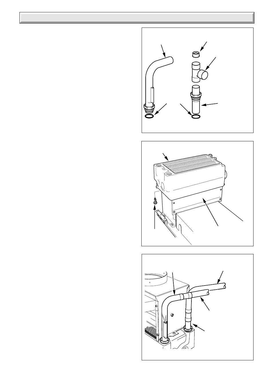
Diagram 4.2
Diagram 4.3
6839
HEAT
EXCHANGER
SECURING
SCREWS (4)
COMBUSTION
CHAMBER
6840
22mm
FLOW
22mm
RETURN
Diagram 4.1
6254
UNEQUAL
TEE PIECE
SEALING
WASHERS
INJECTOR
22mm COPPER PIPE
SUPPLIED WITH
APPLIANCE
(Do not cut)
22mm COPPER
PIPE SUPPLIED
WITH APPLIANCE
(Do not cut)
22mm COPPER PIPE
SUPPLIED WITH
APPLIANCE
(Do not cut)
22mm
COPPER
PIPE
SUPPLIED
WITH
APPLIANCE
(Do not cut)
Pumped Heating and Hot Water
4.1 Preparation
Remove draught diverter assembly, flueway baffles and
fittings pack from carton.
Check contents of fittings pack against packed list.
Remove back boiler body assembly from carton.
4.2 Water Connections
IT IS EXTREMELY IMPORTANT THAT NO SERVICE
PIPES ARE ROUTED IN FRONT OF THE BOILER. If the
builder’s opening was previously used for solid fuel all
pipework within should be protected with PVC tape or equal.
Pipework passing through walls of the opening should be
sleeved and made good.
The two heat exchanger connections are supplied in the
fittings pack and MUST be used, see diagram 4.1.
NOTE: Take care when soldering the copper connections not
to damage the sealing washers.
4.3 Pumped Heating with Gravity Domestic
Hot Water
NOTE: The draught diverter assembly and capillaries are
shown to aid plumbing, but would not be fitted at this stage.
All pipework must comply with the current issue of BS5546.
The domestic hot water flow and return pipes must be
28mm.
Refer to diagrams 1.3 and 1.4 for a diagrammatic layout.
If it is necessary to route pipework from both sides of the
builder’s opening, it is recommended that the heat exchanger
is positioned on the combustion chamber so that the gravity
circuits exit on the same side as the boiler connections.
If the heat exchanger connections are opposite hand to that
required, the heat exchanger can be turned, as follows,
remove the four screws securing the heat exchanger to
combustion chamber, see diagram 4.2. Turn heat
exchanger, refit the four screws.
It is recommended that pumped heating connections are pre-
piped as in diagram 4.4.
Note: The diagram 4.4 shows two methods “A” and “B” of
plumbing the flow pipe.
The central heating return must have the injector fitted on
both methods “A” and “B”, see diagram 4.4 for fitting the
injector.
4.4 Pumped Heating and Hot Water
NOTE: The draught diverter assembly and capillaries are
shown to aid plumbing, but would not be fitted at this stage.
Refer to diagram 1.5 for a diagrammatic layout.
If it is necessary to route pipework from both sides of the
builder’s opening it is recommended that the heat exchanger
is positioned on the combustion chamber such that the flow
pipe exits on the same side as the boiler connections.
It is recommended that the pumped return is pre-piped as in
diagram 4.3.
If the heat exchanger connections are opposite hand to that
required, turn in the same manner as described in Section
4.3 paragraph 6.