5 electrical wiring – Glow-worm 56/3 Back Boiler User Manual
Page 15
15
221724B
Diagram 5.4
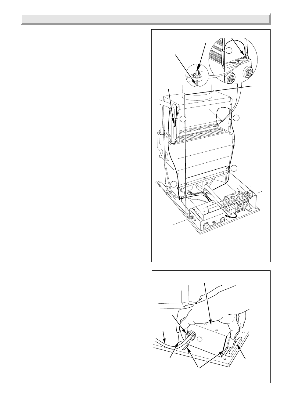
Diagram 5.5
6879
7091
LEFT HAND CLIPPING POSITIONS A and B
RIGHT HAND CLIPPING POSITIONS C and D
OVERHEAT
CUT-OFF
DEVICE
CONTROL THERMOSTAT
PHIAL
RETAINING
LIP
CONTROL
BOX
A
B
C
D
5.3 Boiler Control Box
Taking care that the POWER IS OFF.
Remove the control box, hold with both hands squeeze tilt
forward and unhook, see diagram 5.5.
Remove the gas valve lead.
Thread the mains cable through the side of the box, see
diagram 5.6.
The mains cable outer insulation must not be cut back
external to the clamp.
When making connections, make sure that the earth
conductor is made of a greater length than the current
carrying conductors, so that if the cable is strained the earth
conductor would be the last to become disconnected.
Connect the incoming mains earth conductor to the 3 way
terminal block, see diagram 5.6.
Connect the incoming mains neutral conductor to N and
boiler control live to Ls.
Restrain the mains cable with the clamp supplied.
NOTE: If a Burnt Ember Fire Front is to be fitted a four core
mains supply cable will be required and connected as
diagram 5.8.
5.4 Testing - Electrical
Checks to ensure electrical safety must be carried out by a
competent person.
After installation of the system, preliminary electrical system
checks as below should be carried out,
1. Test insulation resistance to earth of mains cable.
2. Test the earth continuity and short circuit of all cables.
3. Test the polarity of the mains.
4. With the mains supply off.
Refit the control box,.
Refit the gas valve electrical plug.
5.5 Overheat cut-off device (sealed systems
only).
A Kit No. 459033 is available with fitting instructions.
5 Electrical Wiring
SLOT
RETAINING
LIP
MAINS
CABLE
CLAMP
RETAINING
PIN
C