1 general – Glow-worm 56/3 Back Boiler User Manual
Page 5
5
221724B
C
L
BOILER
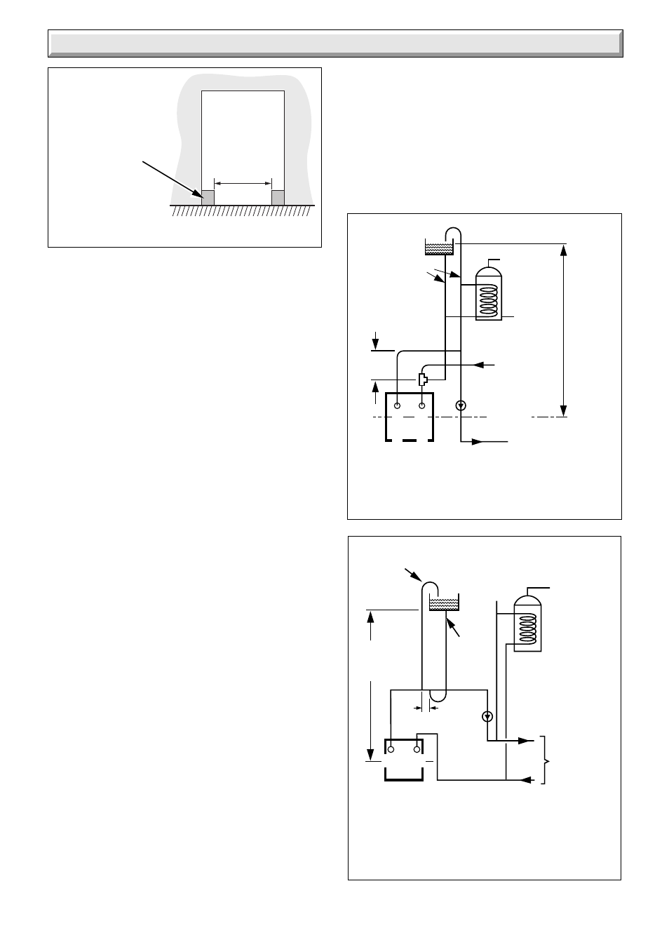
Diagram 1.4
1 General
1.13 BSI Certification
This appliance is certificated to the current issue of BS6332
Part 1 invoking the current issue of BS5258 Part 8 for safety
and performance. It is, therefore, important that no alteration
is made to it without permission, in writing, from Hepworth
Heating Ltd.
Any alteration that is not approved by Hepworth Heating Ltd.,
could invalidate the BSI Certification of the boiler, warranty
and could infringe the current issue of the Statutory
Requirements.
CE Mark
The CE mark on this appliance shows compliance with:
1. Directive 90/396/EEC on the approximation of the Laws
of the Member States relating to appliances burning gaseous
fuels.
2. Directive 73/23/EEC on the harmonization of the Laws of
the Member States relating to electrical equipment designed
for use within certain voltage limits.
3. Directive 89/336/EEC on the approximation of the Laws
of the Member States relating to electromagnetic
compatibility.
This boiler meets the requirements of Statutory Instrument,
No. 3083, The Boiler (Efficiency) Regulations, and therefore
is deemed to meet the requirements of Directive 92/42/EEC
on the efficiency requirements for new hot water boilers fired
with liquid or gaseous fuels.
Type test for purposes for Regulation 5 certified by: Notified
body 0086.
Product/production certified by: Notified body 0086.
1.14 Inhibitor
Attention is drawn to the current issue of BS5499 and
BS7593 on the use of inhibitors in central heating systems.
If an inhibitor is to be used, contact a manufacturer for their
recommendations as to the best product to use.
If using in an existing system take special care to drain the
entire system, including the radiators, then thoroughly
cleaning out before fitting the boiler whether or not adding an
inhibitor.
6242
BOILER
22mm
CENTRAL
HEATING
RETURN
28mm
DISTRIBUTOR
TUBE IN RETURN
CONNECTION
22mm
CENTRAL
HEATING
FLOW
FLOW
RETURN
INDIRECT
CYLINDER
27 METRES
MAXIMUM
IMPORTANT
DIMENSION
NOT LESS
THAN 145mm
C
L
PUMPED HEATING &
GRAVITY DOMESTIC HOT
WATER (DIAGRAMMATIC)
FULLY PUMPED SYSTEM
(DIAGRAMMATIC)
Diagram 1.5
The COLD FEED PIPE may be connected to the flow
pipe, adjacent to the open vent pipe as shown .
(THERE MUST ALWAYS BE A COLD WATER PATH
TO THE RETURN CONNECTION Of THE BOILER.)
22mm MIN
OPEN VENT
INDIRECT
CYLINDER
MANUAL
AIR VENT
1 metre MIN
27 metres MAX
15mm
COLD
FEED
PUMP
HEATING
CIRCUIT
150mm MAX
7218
* CORNER IN-FILL
(not required to be
full depth of opening)
405 mm. MIN.
Diagram 1.3
6408
FRONT
OPENING