6 commissioning – Glow-worm 56/3 Back Boiler User Manual
Page 18
18
221724B
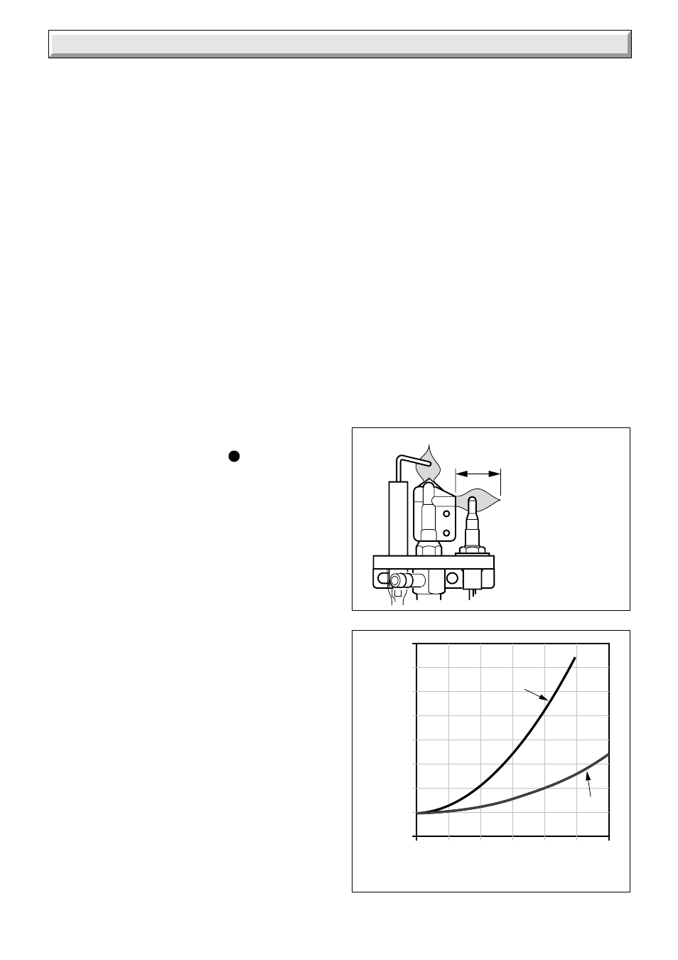
Diagram 6.3
PRESSURE LOSS (mm head of water)
FLOW RATE (litres / minute)
700
With injector
fitted
Without
injector fitted
600
500
400
300
200
100
0
5
10
15
20
25
30
0
-100
7296
6 Commissioning
If the boiler is used with a Miami 3 or Melody 3 fire front it is
permitted to increase the output to 16.4 kW (56000) Btu/h).
If adjustment is required, TEN MINUTES after lighting,
remove cover “G” and turn adjustment screw, anti-clockwise
to suit system design heat input.
Should any doubt exist, the gas rate should be checked at
the gas meter.
The rate of the back boiler should be within the range,
For Saxony, Black Ash, Brown Ember:
1.15m
3
/h (40.5ft
3
/h) to 1.86m
3
/h (65.7ft
3
/h)
For Melody, Miami:
1.15m3/h (40.5ft
3
/h) to 1.94m
3
/h (68.5ft
3
/h)
Note, if the gas rate is checked, make sure that all other gas
appliances and pilot lights are turned off.
Turn control thermostat knob “A” anti-clockwise to “O” “Off”
position. Remove pressure gauge and replace test point
screw ensure a gas tight seal is made. Replace governor
cover screw “G”.
Relight the back boiler by turning thermostat knob “A”
clockwise to “MAX”.
Use the self adhesive arrow from the fittings pack and stick it
against the relevant heat input figure on the Data Label.
6.2 Testing the Back Boiler Controls
To check the operation of the flame failure device proceed as
follows:
With the main burner alight, slightly push in gas control knob
“B” and then turn it fully clockwise until
is against the
setting point. This will put out the main and pilot burners.
Note, relighting will not now be possible as the safety device
in the gas valve has been activated.
Check that the flame failure device closes within 60 seconds,
indicated by a click from the valve.
DO NOT ATTEMPT TO RELIGHT UNTIL AT LEAST 3
MINUTES HAVE GONE BY.
Relight the pilot and main burner as described in the relevant
part of Section 6.1.
Check that the boiler thermostat and any external controls
operate the back boiler correctly.
6.3 Clearance of Products
A clearance of products (spillage) test must be carried out
after installation of the back boiler and its fire.
Before fitting the fire check that the heat exchanger baffle is
fitted and seated correctly, see Section 4.8.
Details of the necessary tests to be carried out will be found
under “TEST FOR CLEARANCE OF PRODUCTS” in the fire
Installation Instruction Booklet.
Note: This test must only be carried out after the fire front
has been fitted to the back boiler unit.
6.4 Commissioning the System
Set all controls to operate the heating system. Adjust
circulating pump and balance the system to give a
temperature drop across the boiler of 11
o
C (20
o
F). At the
appropriate flow rate, the resistance of the back boiler can be
found by reference to diagram 6.3.
There should be no undue noise in the pipework or heat
emitters. There must be NO pumping over of water or entry
of air at the open vent pipe above the feed and expansion
cistern.
Make sure the back boiler thermostat knob “A” is turned
clockwise to “MAX” against the setting point, allow the water
to reach maximum working temperature. Examine the
system for water soundness.
Turn the thermostat knob “A” anti-clockwise to “Off” and
rapidly drain the system whilst still hot, to complete the
flushing process.
Refill the system, vent and check again for water soundness.
Fire Front Installation and Servicing Instructions are packed
with the fire.
Diagram 6.2
6357
13mm
FLAME
DIMENSION