6 commissioning – Glow-worm 56/3 Back Boiler User Manual
Page 17
17
221724B
6 Commissioning
6.1 Commissioning the Back Boiler
Before commissioning the back boiler, the whole of the
system should be thoroughly flushed out with cold water with
the circulation pump removed. Replace the pump, fill the
system and examine for water soundness. Vent air from the
system and pump.
The back boiler unit is fitted with a flue blockage safety
device, which will shut it down if there is a lack of oxygen.
The principle by which this operates is that when there is a
depletion of oxygen resulting from a build up of combustion
products, flame on the pilot light will become unstable and lift
up off the thermocouple. This will deactivate the mag unit in
the gas control valve, cutting off the gas supply.
If the back boiler unit shuts down frequently for no apparent
reason the first things to be checked are the chimney and air
inlets into the room. Any problems found must be put right,
by a competent person, and a full operational test carried
out before the back boiler unit is used again.
The flue blockage safety device incorporates the electrode,
thermocouple and pilot assemblies.
The flue blockage safety device MUST NOT be adjusted or
disconnected. It must be serviced strictly in accordance with
the instructions in this book. Any unauthorised interference
could result in the device failing to operate, creating a
potentially dangerous situation. If replacing, use only the
correct and approved part.
CAUTION: The following work should be carried out by a
competent person.
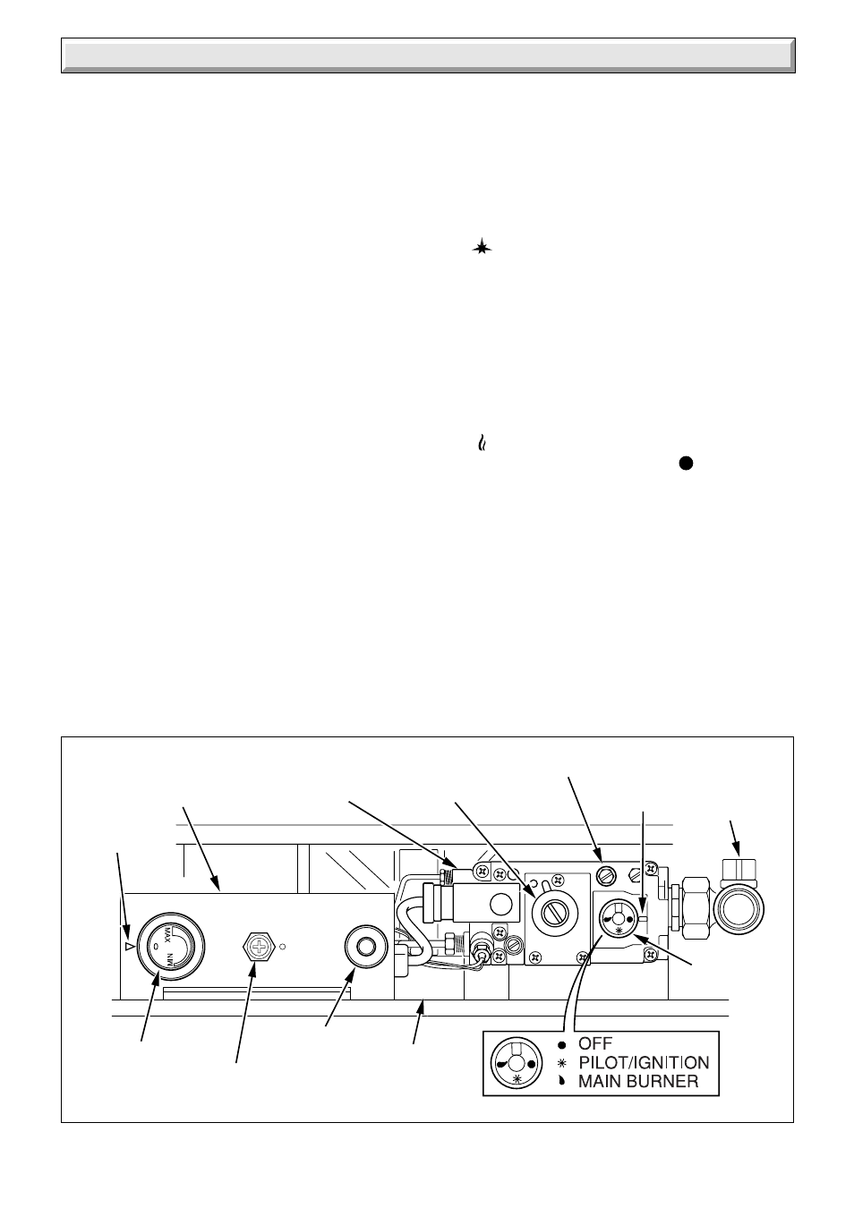
Identify the back boiler controls by reference to diagram
6.1.
Note: Overheat cut-off, see diagram 6.1 is applicable only
where the back boiler unit is incorporated in a sealed water
system.
Open all windows and put out any naked lights, cigarettes
etc.
Test the gas supply for soundness. Purge air in accordance
with the current issue of BS6891.
Check that the electrical supply to the back boiler is switched
off.
Set the thermostat control knob “A” to “Off” that is, fully anti-
clockwise.
Make sure the thermostat phial is fitted correctly, see
diagram 5.4.
Remove the back boiler burner pressure test screw “H” and
connect a suitable pressure gauge.
Turn gas service cock “K” to Back Boiler only “On” position,
see diagram 4.12.
Push in slightly and turn gas control knob “B” anti-clockwise
until
is against the setting point, now push fully in and
hold, at the same time press and release piezo button “D”
until the pilot burner lights.
Note, at this stage air may be present in the pilot supply so
this operation may need to be repeated.
When the pilot burner lights, keep gas control knob “B” fully
pushed in for about 15 seconds. If the pilot burner fails to
stay alight, repeat the lighting procedure but now keep the
control “B” knob pushed in for a little longer.
Check that the pilot flame is stable and has a length as
shown in diagram 6.2.
Push in slightly and turn gas control knob “B” anti-clockwise
until
is against the setting point.
If the gas control knob “B” is turned until
is against the
setting point, a safety lock prevents it being turned on again
until the thermocouple has cooled. NO ATTEMPT SHOULD
BE MADE TO TURN THE CONTROL KNOB “B” UNTIL AT
LEAST 3 MINUTES HAVE GONE BY.
Switch on electrical supply and set any remote controls that
is, clock, thermostats and the like, for heating. Refer to
control manufacturers’ instructions for specific details.
Turn thermostat knob “A” clockwise until “MAX” is against the
setting point. The main burner should now light.
Test for gas soundness using a suitable leak detection fluid.
The back boiler is supplied preset to a maximum heat output
setting of 15.8 kW (54000 Btu/h) but may be adjusted to suit
design requirements.
This value 15.8 kW must not be exceeded when using the
boiler in combination with a Brown Ember 3, Black Ash 3 or
Saxony 3 fire front.
Diagram 6.1
6822
CONTROL BOX
CONTROL
THERMOSTAT
KNOB “A”
BURNER PRESSURE
TEST POINT “H”
GAS
CONTROL
VALVE “J”
SETTING
POINT “C”
GAS
CONTROL
KNOB “B”
GOVERNOR
ADJUSTMENT
COVER SCREW “G”
PIEZO UNIT
BUTTON “D”
BOILER DATA
BADGE “E”
POINTER
“F”
GAS
SERVICE
COCK “K”
OVERHEAT
CUT-OFF DEVICE
(sealed systems only)