5 electrical wiring – Glow-worm 56/3 Back Boiler User Manual
Page 14
14
221724B
5 Electrical Wiring
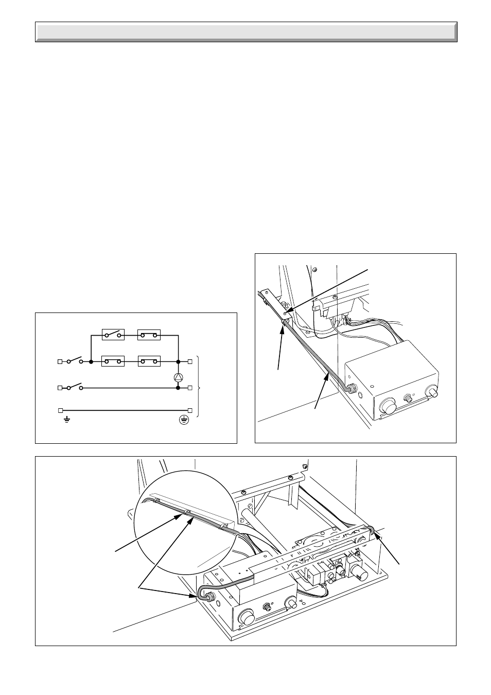
Diagram 5.2
Diagram 5.3
6878
6871
5.1 General
WARNING. This boiler must be earthed.
ISOLATE THE ELECTRICAL SUPPLY BEFORE DOING
ANY WIRING
All of the electrical installation must be correctly earthed and
be in accordance with the current issue of BS7671 and be
carried out by a competent person.
The boiler electrical supply is 230V~ 50Hz, fused at 3A. A
double pole isolating switch, having a minimum contact
separation of 3mm in both poles should be used.
The boiler will only require a permanent live if a fire front with
lights or ignition is to be fitted.
External controls are connected to the live 'Ls' terminal on
the 3 way terminal block, as an example see diagram 5.1.
Supply cable should be (85
o
C) PVC insulated type to the
current issue of BS6500 Table 16, not less than 0.75mm
2
(24/0.20mm).
NOTE: The supply to the boiler and any remote control must
be through the same isolating switch or plug and socket.
It is preferable to have the boiler electrical supply cable
entering the builder’s opening at the left.
If the cable has to be routed down the left hand side of the
combustion chamber the heat shield assembly supplied in
the fittings pack must be used and the cable routed through
the clips, see diagram 5.2.
HEAT
SHIELD
ASSEMBLY
ELECTRICAL
SUPPLY
CABLE
CABLE
CLIPS (3)
ELECTRICAL
SUPPLY
CABLE
Diagram 5.1
6452
Froststat
Pipestat
Roomstat
Programmer
Pump
Ls
N
E
L
N
E
Double
Pole
Switchspur
3 Way
terminal
block at
Appliance
If right hand access is required fit the three clips from the
fittings pack to the combustion chamber extension and route
the cable down the right hand side of the combustion
chamber. Keep the cable well clear of hot surfaces, see
diagram 5.3.
NOTE: The boiler electrical supply cable must not be
routed along the back of the appliance.
The cable must be kept well clear of hot surfaces.
When fitting the back boiler unit do not trap the cable.
5.2 Control Thermostat Phial
Unwind the capillary avoid kinking, make sure that the
capillary is positioned so that it passes through the cut out in
the side of the control box, see diagram 5.7. Route the
capillary well clear of any part of the back boiler which
becomes hot. Use the capillary clips, supplied. Secure the
capillary and push the phial into the pocket, secure the phial
with the retaining pin supplied, see diagram 5.4. Again make
sure that the capillary is not touching the casting.
NOTE: When fitting the phial into the phial pocket use the
heat sink compound supplied in the fittings pack.
CABLE CLIPS
ELECTRICAL
SUPPLY
CABLE