10 replacement of parts – Glow-worm 56/3 Back Boiler User Manual
Page 25
25
221724B
10 Replacement of Parts
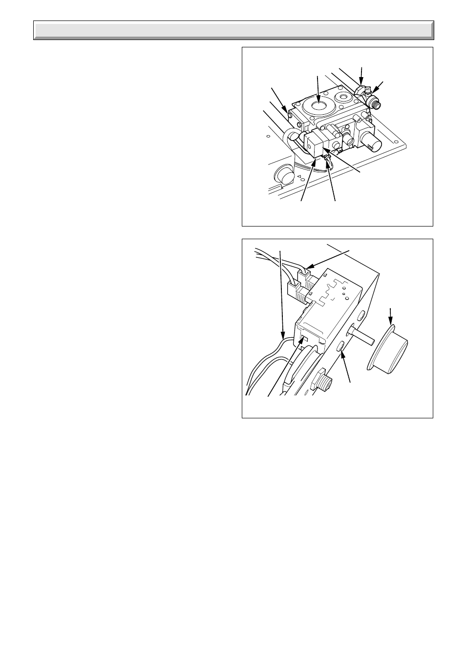
Diagram 10.2
7094
Diagram 10.3
7159
THERMOCOUPLE
NUT
PILOT TUBING
NUT
CONTROL
KNOB
ELECTRICAL
CONNECTIONS (2)
CONTROL
THERMOSTAT
SECURING
SCREW (2)
SECURING
SCREWS
(4)
GAS CONTROL
VALVE ELECTRICAL
PLUG
GAS
CONTROL
VALVE
GAS
SERVICE
COCK
UNION
NUT
CAPILLARY
10.10 Control Thermostat
Remove the combustion chamber extension, see diagram
4.5.
Remove the control box refer to the relevant parts of Section
8.3.
Remove the control thermostat phial and unclip the capillary
tube, see diagram 5.4.
Remove the control knob, see diagram 10.3.
Remove the two electrical connections from the control
thermostat, see diagram 10.3.
Remove the two securing screws and remove the control
thermostat and capillary from the cut out slot, see diagram
10.3.
When refitting the capillary should pass through the cut out
slot on the control box.
The capillary tube must not touch any part of the back boiler
that becomes hot, re-clip the capillary tube and push the
phial into the pocket.
NOTE: When fitting the phial use heat sink compound.
When refitting refer to diagram 5.4.
10.11 Over Heat Cut-off Device (Sealed
systems only)
Remove the combustion chamber extension, see diagram
4.5.
Remove the control box refer to the relevant parts of Section
8.3.
Remove the over heat phial and unclip the capillary tube, see
diagram 5.4.
Remove the locknut, see diagram 10.4.
Remove the over heat electrical connections, see diagram
10.4.
Remove the over heat cutoff device and capillary from the
cut out slot, see diagram 10.4.
NOTE: When refitting, the capillary should pass through the
cut out slot on the control box, see diagram 10.4.
When refitting refer to the wiring diagram 5.8.
The capillary tube must not touch any part of the back boiler
that becomes hot, re-clip the capillary tube and push the
phial into the pocket.