8 servicing – Glow-worm 56/3 Back Boiler User Manual
Page 22
22
221724B
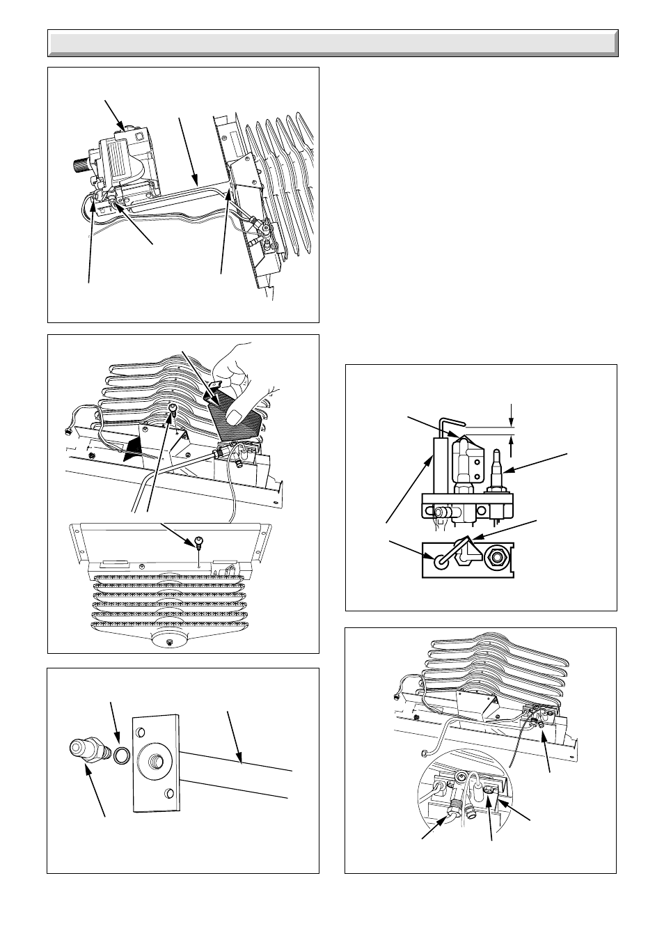
Diagram 8.8
6301
EARTH
POST
FRONT
VIEW
Diagram 8.9
6207
FLUE
BLOCKAGE
SAFETY
DEVICE
EARTH
POST
ELECTRODE
TOP VIEW
SPARK GAP
3 +1 or -0.5
SECURING
SCREW (2)
PILOT TUBE
NUT
THERMOCOUPLE
Diagram 8.5
Diagram 8.6
6191
6905
GAS
CONTROL
VALVE
PILOT TUBE
NUT
GAS
MANIFOLD
SECURING
SCREWS
THERMOCOUPLE
NUT
LINT ARRESTER
8 Servicing
Diagram 8.7
6834
COPPER
WASHER
MAIN BURNER
INJECTOR
GAS
MANIFOLD
SECURING SCREW (4)
8.10 Back Boiler Flueways
Remove the spigot duct, see diagram 8.10.
Remove the draught diverter plate by slackening the two side
securing screws and removing the rear securing screw, see
diagram 8.10.
Lift out the flueway baffles, see diagram 8.11.
Place a sheet of paper in the base of the combustion
chamber.
Clean the boiler flueways with a suitable stiff brush.
To make sure that the flueways are clean, view with the aid
of a mirror or reflector.
Remove the paper and debris.
When refitting make sure that the baffles are correctly seated
in the back and middle flueways, see diagram 8.11.
NOTE: If the heat exchanger has been turned the baffles
must still be fitted into the back and middle flueways.
Refit the draught diverter plate.
Refit the control/burner assembly.