8 servicing – Glow-worm 56/3 Back Boiler User Manual
Page 21
21
221724B
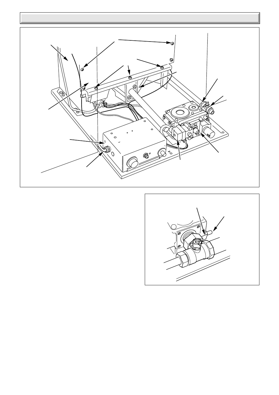
8.4 Burner
Disconnect the pilot tube nut and the thermocouple nut from
the gas control valve, see diagram 8.5.
Remove the screws which locate the gas manifold to burner,
see diagram 8.5.
The gas control valve can now be lifted clear of the burner.
Clean the burner as necessary, do not use a brush with
metallic bristles.
8.5 Lint Arrester
Remove the four securing screws to disengage the two lint
arresters, see diagram 8.6.
Clean the lint arresters as required.
8.6 Main Burner - Injector
Inspect the main burner injector for damage or blockage,
clean or replace as necessary. If replacing ensure the new
copper washer is fitted, see diagram 8.8.
Do not use a wire or sharp instrument to clean the injector
hole.
8.7 Flue Blockage Safety Device Assembly
Gain access as relevant part of Section 8.3. Remove any
dust and lint, inspect the pilot for damage. Remove the
sensing tube adapter, to clean, blow through, do not use a
wire or sharp instrument. Inspect the electrode and
thermocouple for wear or damage, clean, or replace as
necessary the flue blockage safety device, see diagram 8.8.
To remove the safety device, disconnect the pilot tube nut
and two securing screws, see diagram 8.9.
Ensure the electrode is in line with the earth post and the
spark gap is as shown in diagram 8.8.
8 Servicing
Diagram 8.3
7093
GAS
CONTROL
VALVE
COMBUSTION
CHAMBER
GAS SERVICE
COCK
MAINS
ELECTRICAL
CABLE
COMBUSTION CHAMBER
SECURING SCREWS (2)
GAS
MANIFOLD
SECURING
SCREW (2)
COMBUSTION
CHAMBER
FRONT COVER
UNION
NUT
BURNER SECURING
SCREWS (3)
CONTROL
BOX
Note: When reassembling the burner assembly the following
points should be observed:
a) Make sure that the lint arresters are engaged in the
correct position on the burner support bracket.
b) DO NOT replace the combustion chamber control/burner
assembly into the back boiler until the boiler flueways
servicing has been carried out.
8.8 Ignition Lead
Inspect the ignition lead for wear or damage, clean or
replace as necessary.
GAS
CONTROL
ELECTRICAL
PLUG
Diagram 8.4
7095
GAS CONTROL
RETAINING PIN
GAS CONTROL VALVE
SECURING BRACKET