Installation, Dc b e a, 5 systempro control unit – Glow-worm Clearly Hybrid - Back-up Module System User Manual
Page 16: 1 wiring to the systempro control unit, 2 internal connection, 230v connection (high voltage), 24v connection (low voltage)
0020096317_01 - 08/10 - Glow-worm
- 14 -
INSTALLATION
6.5
Systempro control unit
• The electrical installation in the dwelling must permit the
power supply to the equipment to be isolated by a double
pole isolation switch and be fused. The double pole isolation
switch must incorporate a gap of 3mm between the contacts.
• Use a power cable suitable for the mains connection,
minimum 0.75 mm. If the cable is damaged, it must be
replaced by a qualified engineer.
6.5.1
Wiring to the Systempro control unit
D
C
B
E
A
5
1
2
3
4
Key
1 230 V power cable
2 break out tab
3 Anti-tamper connection
4 Power connection
5 Control unit
• Gently remove the break out tab (2) from the control unit with
pliers (A).
• Connect the control unit following the order (B) to (D).
• Pass the power cable (1) through the anti-tamper connector
(3).
• Connect the power supply to the 230 V connector (4)
following the instructions given on the connector.
• Tighten the power cable (1) in the anti-tamper connector (3).
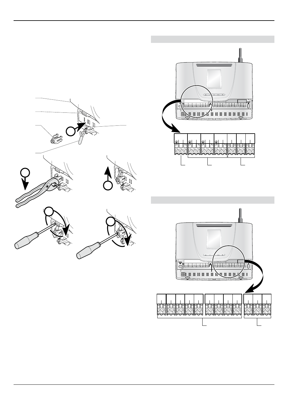
6.5.2
Internal connection
230V connection (High voltage)
1
3
L
N
230V~
1
3
L
N
REL1
1
3
L
N
REL2
1
3
L
N
REL3
1
2
L
N
REL4
1
2
L
N
REL5
1
2
L
N
IN1
3
2
1
Key
1 230 V connector (3-pin: earth / neutral / live)
2 Connectors (3 pins: earth / neutral / live): ReL1, ReL2 and
ReL3
3 Connectors (2 pins: live / neutral): ReL4, ReL5 and IN1
24V connection (Low voltage)
1
2
2
1
OUT1
1
2
2
1
OUT2
1
2
2
1
OUT3
1
2
2
1
IN2
1
2
2
1
IN3
1
2
2
1
NTC1
1
2
2
1
NTC2
1
2
2
1
NTC3
1
2
2
1
NTC4
1
2
-
+
EBUS
1
2
-
+
EBUS
1
2
-
+
EBUS
2
1
Key
1 Connectors (2 pins) OUT1, OUT2, OUT3, IN2, IN3, NTC1, NTC2,
NTC3 and NTC4
2 ebUS connectors (2 pins)