Installation, 6 electrical connections – Glow-worm Clearly Hybrid - Back-up Module System User Manual
Page 14
0020096317_01 - 08/10 - Glow-worm
- 12 -
INSTALLATION
5.3
Heating circuit
5.3.1
Connection from the hydraulic module to
the heating circuit
i
Make the connection limiting the load losses to a
minimum (the circuit should be as short as possible,
avoid bends and narrow sections...).
6
5
7
1
3
4
2
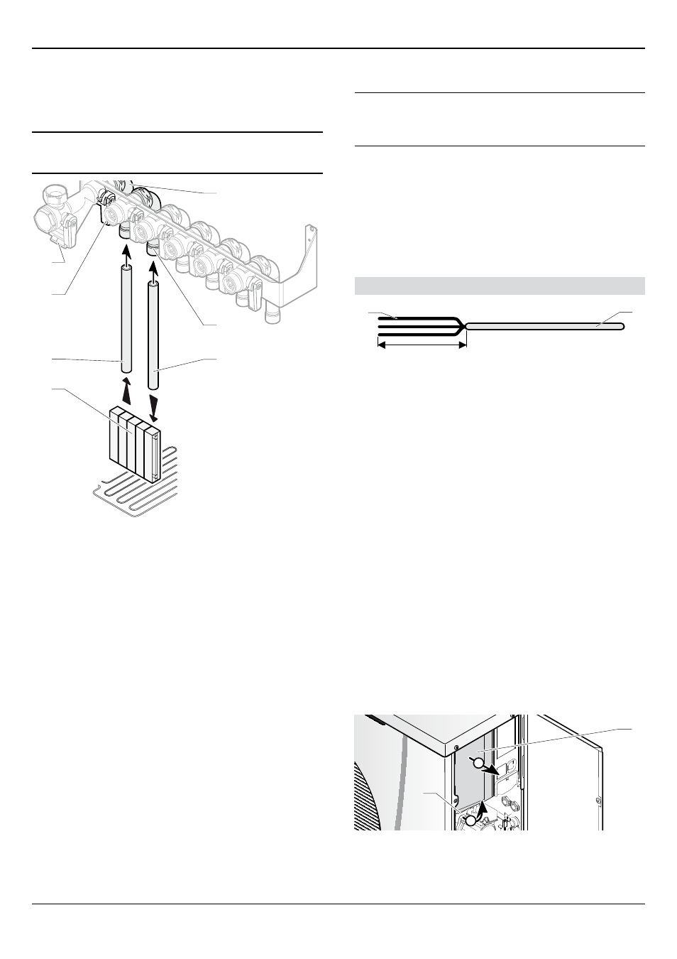
Key
1 Heating circuit
2 Return heating tubing leading to the hydraulic module (not
included)
3 Return heating circuit ¼ turn shut-off valve leading to the
hydraulic module (not included)
4 Return heating circuit filter leading to the hydraulic module
(not supplied)
5 Return heating connection (Ø ¾") leading to the hydraulic
module
6 flow heating connection (Ø ¾") leading to the hydraulic
module
7 flow heating tubing leading to the hydraulic module (not
included)
• Connect a pipe (2) to the return connection (5) leading to the
hydraulic module.
• Connect a pipe (7) to the flow connection (6) leading away
from the hydraulic module.
• Connect the pipes (2) and (7) to the heating circuit.
6 electrical connections
e
Incorrect installation can cause electric shock or
appliance damage. The electrical connection of
the appliance must be made only by a qualified
engineer.
The appliance must be connected directly to an accessible,
fixed, switched, electrical outlet.
The manufacturer declines any responsibility for damages to
persons or others caused by the incorrect installation of the
appliance earthing. This includes failure to comply with current
standards.
Electrical components have been tested to meet the equivalent
requirements of BSEN 7671 and the BEAB regulations.
Main board
20 mm max.
1
2
Key
1 electrical wires
2 Insulation
When you connect the electrical wires to a connector on the
electronic board:
• Maintain a maximum distance of 20 mm between the
connector and the outer insulation.
• If using single core wires are used ensure that they are
wrapped together in an insulating sheath.
6.1
Heat pump
The cables connecting the isolator and the heat pump must be:
- suitable for a fixed installation.
- weather resistant.
- equipped with wires adapted to appliance’s power rating.
• Connect the heat pump to an electrical panel via an
independent protection system (20A differential breaker with
at least 3 mm between each contact).
Additional protection may be required during installation to
ensure overvoltage category II.
6.1.1
Access to main board
B
A
2
1
Key
1 Handle
2 box
• Remove the box (2) by pulling it toward you using the handle
(1).