Installation, 8activating the heat pump – Glow-worm Clearly Heat Pumps - Standalone Module System User Manual
Page 21
0020096321_00 - 07/10 - Glow-worm
- 19 -
INSTALLATION
1
2
3
4
A
B
5
6
8
7
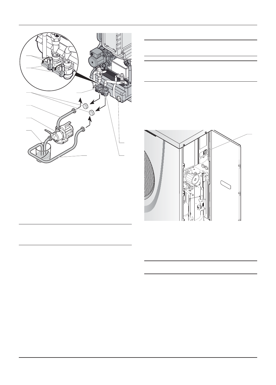
Key
1
Glycol container (*)
2
Filling pump (*)
3
Hose leading to the fi lling pump output (*).
4 Cap
5
3-way valve with shut-off valve for fi lling
6 Manometer
7
3-way valve with shut-off valve for fi lling
8
Hose leading to the fi lling pump return (*)
(*) Not supplied with the appliance
A Valve
in
fi lling mode
B
Valve in normal operating mode
i
If the domestic hot water cylinder option is installed
on the system, position the kit 3-way valve to the
MAN position to ensure complete fi lling of the heat
pump circuit.
• In order to drain the glycol circuit after fi lling, use a fi ll pump
(2).
• Remove the caps (4) from the valves (5) and (7).
• Connect
the
fi lling pump hose (3) to the valve (5).
• Insert the hose (8) into the container and (1) and connect it
to the valve (7).
• Open valves (5) and (7) in (A) position as shown in the
illustration above.
• Start
the
fi ll pump (2) and fi ll the glycol circuit.
• Continue running the fi lling pump until completely purged of
air (8).
• Close the air trap located on the heat pump.
• Close the valve (7) in (B) position and ensure the glycol
circuit is left with a pressure of between 1.5 and 2 bars with
the aid of the manometer (6).
• Close the valve (5) in (B) position and stop the fi lling pump.
i
If the domestic hot water cylinder option is installed on
the system, reposition the kit 3-way valve to the AUTO
position
i
The level of glycol may decrease during the
fi rst month following the commissioning of the
installation. It may also vary in accordance with the
outdoor temperature.
Any residue of glycol solution should be kept in an appropriate
container to be re-used for the next fi lling.
• Ensure any leftover glycol solution is left with the end user
and retained in a safe place.
8
Activating the heat pump
1
Key
1 ON/OFF
button
• Switch ON the circuit breaker which is located on the
electrical panel and connected to the heat pump.
• Switch ON the heat pump button (1). Check that the green
LED located on the heat pump’s motherboard is on.
i
To locate the LEDs on the PCB, see the "Wiring
diagram" chapter in the heat pump instructions.