18 replacement of parts – Glow-worm 23c User Manual
Page 41
41
2000225000B
18 Replacement of Parts
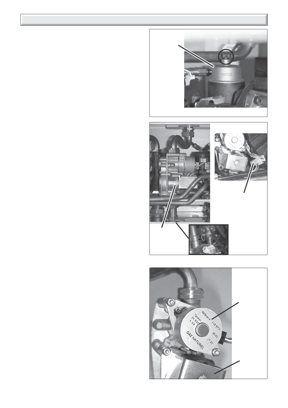
18.27 Automatic air vent, refer to diagram
18.18.
Before starting refer to the front of Section 18 Important
information.
• Remove the front panel, refer to Section 15.3.
• Lower the control panel, refer to Section 15.4.
• Drain down the boiler only, refer to relevant part of diagram
18.1.
• Unscrew to remove automatic air vent.
• After fitting replacement automatic air vent ensure the cap is
open.
18.28 Gas Control valve, refer to diagram
18.19.
Before starting refer to the front of Section 18 Important
information.
• Remove the front panel, refer to Section 15.3.
• Lower the control panel, refer to Section 15.4.
• Disconnect gas supply pipe union nuts at the gas control valve.
• Disconnect injector supply pipe union nut at the gas control
valve. Slacken the union nut at the burner injector bar.
• Remove gas control valve retaining clip from the underside of
gas control valve.
• Ease gas control valve forwards and disconnect electrical
connections to gas control valve.
Note: The washers must be kept for use on reassembly.
• Withdraw gas control valve assembly.
• After fitting replacement gas control valve test for gas
soundness.
18.29 Gas control valve stepper motor
Before starting refer to the front of Section 18 Important
information.
• Remove the front panel, refer to Section 15.3.
• Lower the control panel, refer to Section 15.4.
• Disconnect the electrical connection from stepper motor, see
diagram 18.19.
• Remove the two screws securing stepper motor to the gas
control valve, see diagram 18.20.
• Fit replacement gas control valve stepper motor.
• Note: Take care not to damage the 'O' ring.
18.30 Discharge safety valve, refer to diagram
18.21.
Before starting refer to the front of Section 18 Important
information.
• Remove the front panel, refer to Section 15.3.
• Lower the control panel, refer to Section 15.4.
• Undo discharge pipe union nut.
• Pull out slotted metal clip from valve body and remove valve.
9973
Diagram 18.18
9781
Diagram 18.19
GAS
CONTROL
VALVE
➜
➜
➜
➜
➜
10011
10010
AUTOMATIC
AIR VENT
10029
Diagram 18.20
STEPPER
MOTOR
➜
➜
GAS
CONTROL
VALVE
STEPPER
MOTOR
ELECTRICAL
CONNECTION