Glow-worm 23c User Manual
Page 38
38
2000225000B
18 Replacement of Parts
18.17 User interface board, refer to diagram
18.11.
Before starting refer to the front of Section 18 Important
information.
• Remove the front panel, refer to Section 15.3.
• Lower the control panel, refer to Section 15.4.
• Unclip control panel user interface and hinge forward . Do not
strain the cables.
• Disconnect the electrical connections from the user inter face
board.
• Remove the two user inter face board retaining screws.
• Remove the user inter face board.
18.18 Mains switch, see diagram 18.11.
Before starting refer to the front of Section 18 Important
information.
• Remove the front panel, refer to Section 15.3.
• Lower the control panel, refer to Section 15.4.
➜
➜
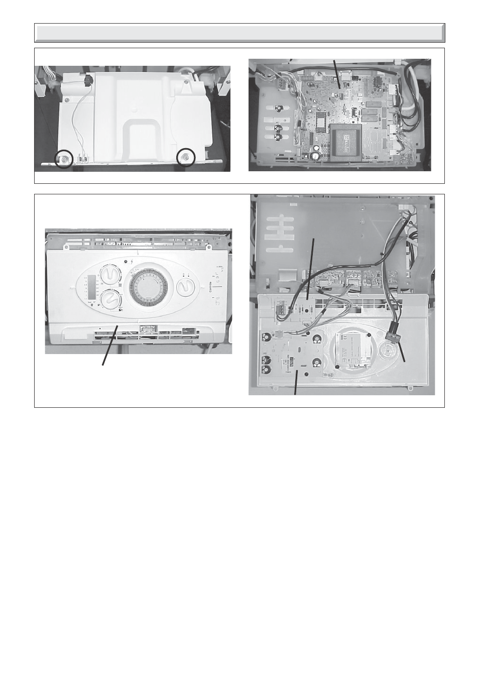
Diagram 18.10
PCB (CONTROL BOARD)
CONTROL
BOARD
COVER
Diagram 18.11
➜
➜
USER INTERFACE BOARD
➜
➜
CONTROL PANEL
10001
10000
10019
9762
➜
• Unclip control panel user interface and hinge forward . Do not
strain the cables.
• Disconnect the electrical connections from the mains switch.
• Remove and replace the mains switch.
18.19 230V Controls board, refer to diagram
18.11.
Before starting refer to the front of Section 18 Important
information.
• Unclip control panel user interface and hinge forward . Do not
strain the cables.
• Disconnect the electrical connection from the 230V controls
board and the electrical connection from printed circuit board
(PCB).
• Remove the 230V controls board retaining screw.
• Remove the 230V controls board.
MAINS
SWITCH
230V CONTROLS
INTERFACE
BOARD