14 settings, 15 routine cleaning and inspection – Glow-worm 23c User Manual
Page 22
22
2000225000B
9532
PRODUCTS
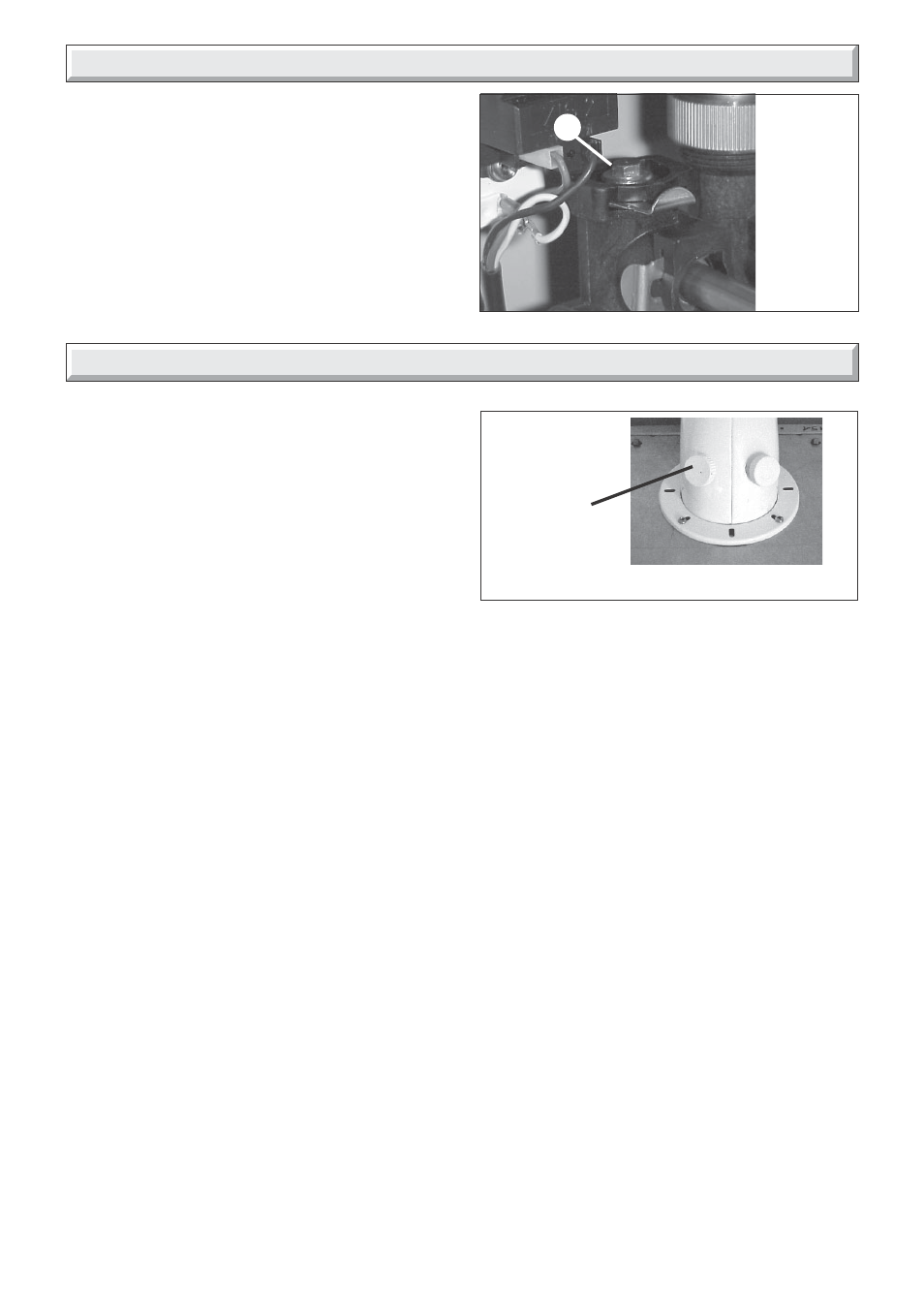
SAMPLING
POINT
Diagram 15.1
REMEMBER, when replacing a part on this appliance, use only
spare parts that you can be assured conform to the safety and
performance specification that we require. Do not use
reconditioned or copy parts that have not been clearly authorised
by Hepworth Heating.
To ensure the continued efficient and safe operation of the
boiler it is recommended that it is checked and serviced at
regular intervals. The frequency of servicing will depend upon
the particular installation conditions and usage, but in general
once a year should be enough.
It is the law that any servicing is carried out by a qualified
registered person.
15.1 Products of combustion check
Note: To obtain a products of combustion reading, unscrew the
left hand sampling point cap on the flue elbow, located on top
of boiler, see diagram 15.1.
Connect the analyser tube onto sampling point.
Refer to the combustion product values in Section 1 Technical
Data.
Switch on the electrical supply and gas supply, then operate the
boiler.
On completion of the test switch off the electrical supply and the
gas supply, remove analyser tube and replace sampling point
cap.
15.2 Service Check and Preparation.
• Isolate boiler from the gas and electrical supplies.
• Drain the Domestic hot water circuit and the boiler, refer to
diagram 15.2.
• On completion check all gas-carrying parts for soundness with
leak detection fluid.
• Remove boiler casing as follows:
Diagram 14.1
9975
14 Settings
A
Bypass
The 23c boiler has a built-in bypass. This must be adjusted
according to the requirements of the system, refer to the flow
rate pressure curve (diagram 1.1). The boiler is supplied with
the built-in bypass open a half a turn. It is adjusted by turning the
bypass screw (a), see diagram 14.1. Turn the screw clockwise
to close the bypass. When using thermostatic radiator valves
(TRV’s) on all of the radiators, it is essential that a separate,
adjustable bypass of 15 mm minimum diameter is fitted between
the flow and return of the heating circuit, see diagram 8.1. Any
bypass must be fitted before system controls.
15 Routine Cleaning and Inspection
15.3 Front panel
• Unscrew and remove the two retaining screws from the bottom
of the front panel.
• Remove front panel by pulling forward and lifting up.
15.4 Control panel
• Lower forwards to gain access to lower part of boiler.
15.5 Sealed chamber cover
• Unclip the two toggle clips holding the sealed chamber cover,
see diagram. 15.3.
• Lift cover up and off pins on the top of the boiler.