Glow-worm 23c User Manual
Page 40
40
2000225000B
18 Replacement of Parts
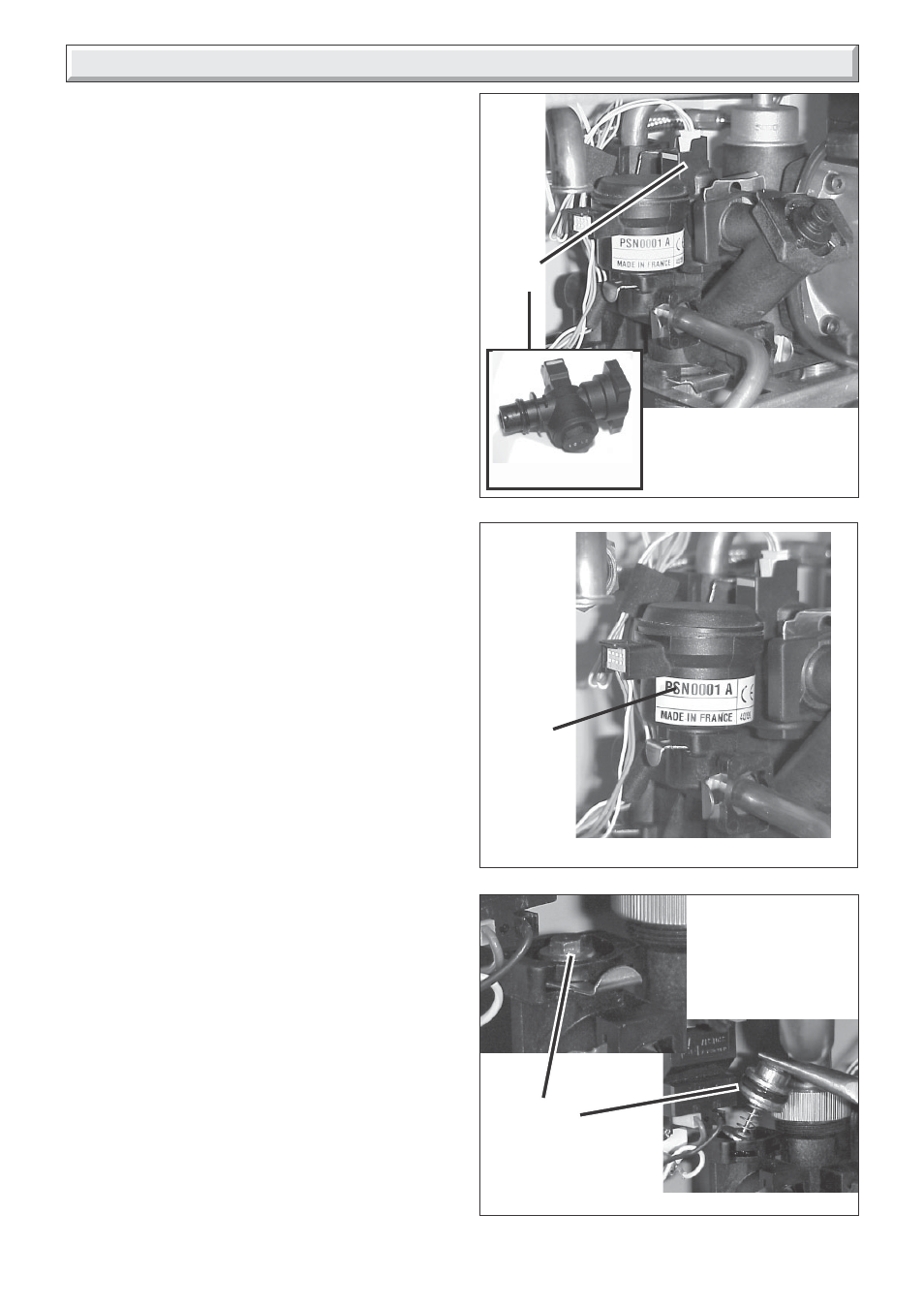
18.24 Water flow sensor, refer to diagram
18.15.
Before starting refer to the front of Section 18 Important
information.
• Remove the front panel, refer to Section 15.3.
• Lower the control panel, refer to Section 15.4.
Drain down the boiler, refer to relevant part of Section 18.1.
• Undo the union on the cold water inlet isolating tap.
• Pull out slotted metal clip securing filling system tap into
housing, swing the tap forwards.
• Pull out the two slotted metal clips retaining the domestic water
inlet filter housing.
• Remove domestic water inlet filter housing.
• Remove electrical connections from water flow sensor.
• Pull off slotted metal clip and remove water flow sensor.
18.25 System water pressure sensor, refer to
diagram 18.16.
Before starting refer to the front of Section 18 Important
information.
• Remove the front panel, refer to Section 15.3.
• Lower the control panel, refer to Section 15.4.
Drain down the boiler, refer to relevant part of Section 18.1.
• Remove electrical connections from water pressure sensor.
• Pull off slotted metal clip and remove water pressure sensor.
18.26 Bypass valve, refer to diagram 18.17.
Before starting refer to the front of Section 18 Important
information.
• Remove the front panel, refer to Section 15.3.
• Lower the control panel, refer to Section 15.4.
Drain down the boiler, refer to relevant part of Section 18.1.
Pull out slotted metal clip and remove bypass valve.
➜
➜
10006
Diagram 18.16
SYSTEM
WATER
PRESSURE
SENSOR
Diagram 18.15
WATER
FLOW
SENSOR
➜
10008
➜
➜
9847
➜
Diagram 18.17
10009
➜
➜
9975
BYPASS
VALVE