16 fault finding – Glow-worm 23c User Manual
Page 27
27
2000225000B
16 Fault Finding
COMPONENT
NORMAL MEASURE
CHECK
Gas control valve
Under demand during ignition sparks:
If 0 Volt:
the gas control valve
Resistance of coil 116Ω
24V dc for 1 to 2 seconds, then
is not faulty.
12Vdc (constant) at the gas control
If 24 Volts and then 12 Volts
valve electrical connection.
but no gas at the burner:
Check if the gas control valve is
stuck. If not, check the
stepper valve.
Adjustment valve
Close the gas inlet:
If the valve does not move:
( step motor)
Dismantle the step motor (screw not
Check the connections at both
sealed in). Trigger a demand and check
motor and control board (PCB).
that the valve opens during the ignition.
Change the motor. Replace the
control board (PCB).
Domestic water flow
To test:
Use a new detector and
connect it electrically in place of
the faulty one . Blow through to
simulate a demand for water.
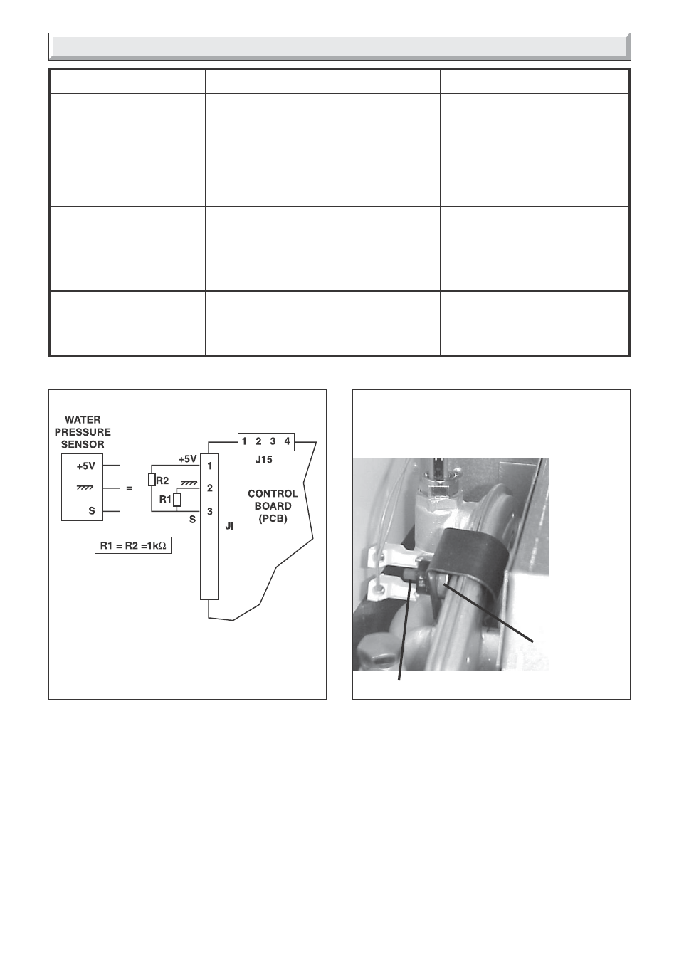
Diagram 16.1
9913
FAULTY WATER
PRESSURE SENSOR
It is possible to replace
the sensor with two 1kΩ
resistors as shown in the
diagram.
Overheat thermostat reset button.
Refer to section 18.10 to locate the overheat thermostat
reset button.
Depress the button to reset.
OVERHEAT
THERMOSTAT
9988
RESET BUTTON
Diagram 16.2