A) (b) (c) (d), 18 replacement of parts – Glow-worm 23c User Manual
Page 34
34
2000225000B
18 Replacement of Parts
IMPORTANT INFORMATION
WARNING: Before commencing the replacement of any
component, isolate appliance from electrical supply and turn off
gas at service cock.
Replacement of parts must be carried out by a competent
person.
When replacing components it may be necessary to renew
sealing washers, gaskets and 'O' rings. If new ones are
supplied with replacement components they must be used.
All parts are replaced in reverse order to removal.
If any gas-carrying components are disturbed, removed or
replaced it will be necessary on completion to check for gas
soundness with leak detection fluid.
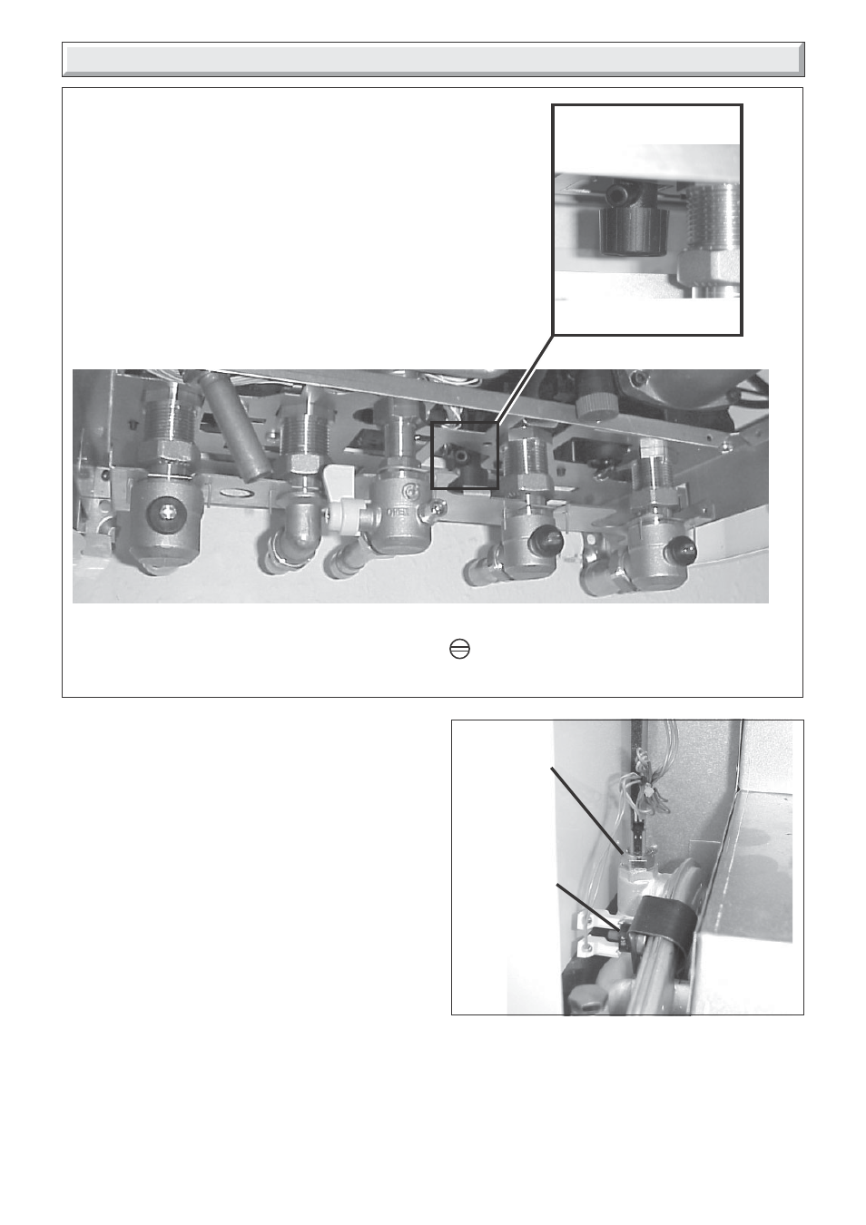
18.1 Central heating thermistor
Before starting refer to the front of Section 18 Important
information.
• Remove the front panel, refer to Section 15.3.
• Lower the control panel, refer to Section 15.4.
• Remove the sealed chamber cover, refer to Section 15.5.
• Locate central heating thermistor on the top left hand side of
the heat exchanger, see diagram 18.2.
Diagram 18.2
9988
CENTRAL HEATING
THERMISTOR
To Drain the central heating circuit
• Open drain valve fitted at the lowest point in the system.
• Allow air into the system by opening a radiator bleed screw or the boilers drain
valve (a).
To Drain the Domestic hot water circuit
• Close boiler isolating valve (c).
• Turn on one or more hot water taps.
To Drain the boiler
• Close isolating screws on the isolating valves (b), (c) and (d) turn from vertical
to horizontal to close.
• Open the boiler drain valve (a).
• Turn on one or more hot water taps.
• Disconnect electrical connections from thermistor.
• Remove the thermistor from the heat exchanger.
• Fit replacement thermistor.
• Refit electrical connections.
Diagram 18.1
9836
(a)
(b)
(c)
(d)
HEATING
RETURN
COLD
WATER IN
HEATING
FLOW
BOILER DRAIN VALVE
Note: Isolating cocks water and gas
are shown in the: OFF position
9839
OVERHEAT
THERMOSTAT