8 piping system installation – Glow-worm 23c User Manual
Page 14
14
2000225000B
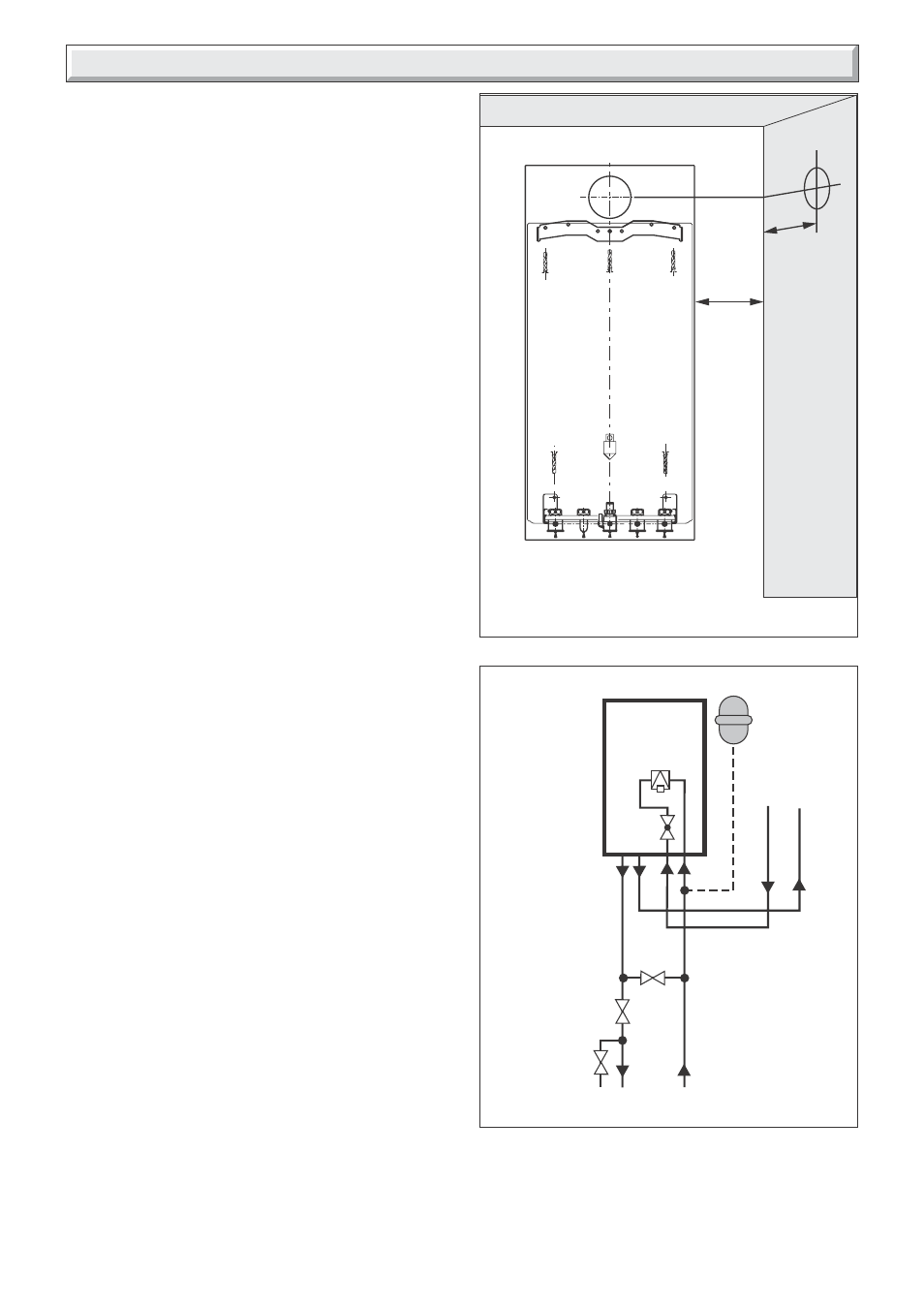
20mm
MIN.
165mm
8.1 Fixing jig, see diagram 7.1
• Remove the contents of the fixing jig pack.
• Secure the left and right hand support brackets to the isolating
valve plate with the securing screws (2 OFF) supplied.
• Connect the five copper connections and sealing washers to
the isolating valves.
1 Heating system connections - Pipe diam. 22mm
2 Hot water system connections - Pipe diam. 15mm
3 Gas connection - Pipe diam. 15mm
8.2 Wall template
• Remove the wall template, follow the instructions given on the
wall template.
• Note: It is important the hanging bracket and service cock
bracket are fitted to a flat and true wall area for correct alignment
with the boiler. If this cannot be achieved it is acceptable to pack
out the service cock bracket to obtain the correct alignment.
• Position the wall template, see diagram 8.1.
• Mark the position of the holes for the hanging bracket and jig.
• Drill, plug and fix the hanging bracket to the wall using suitable
screws (not supplied).
• Check that the hanging bracket is level.
• Drill plug and fix the fixing jig to the wall.
• For horizontal flue system, mark the position for the flue hole
as follows:
8.3 Flue to rear of boiler
• Mark correct position of hole from template.
8.4 Flue to side of boiler
• Mark the horizontal centre line for the hole on the rear wall.
Extend the horizontal centre line to the side wall and mark the
vertical centre line of flue hole as shown in diagram 8.1.
8.5 Cutting the flue hole
• Making allowance for the slope of the flue, cut hole in external
wall, preferably using a core drill. For installations with internal
and external access use a 105 mm diameter core drill.
For installations with internal access only use a 125 mm
diameter core drill.
Important
When cutting the flue hole and when extending the flue centre
line to a side wall, remember that the flue system must have a
fall of about 35 mm per metre of flue DOWNWARD towards the
terminal. There must NEVER be a downward incline towards
the boiler.
8.6 Water connection
Connect the system pipework to the copper connections on the
fixing jig observing the correct flow and return format as shown
in diagram 8.2. Do not subject the isolating valves to heat.
8.7 Gas connection
• The supply from the governed gas meter must be of adequate
size to provide a constant inlet working pressure of 20 mbar (8
in w.g.).
8 Piping System Installation
10038
Diagram 8.1
Diagram 8.2
9898
Control
valve
Flow
Drain
point
Bypass
valve
Domestic
water
Heating
circuit
Return
Additional
expansion
vessel
(if required)
Hot water out
Cold supply in
Boiler
Filling device
Refer to
Section 14
*
*