18 replacement of parts – Glow-worm 23c User Manual
Page 37
37
2000225000B
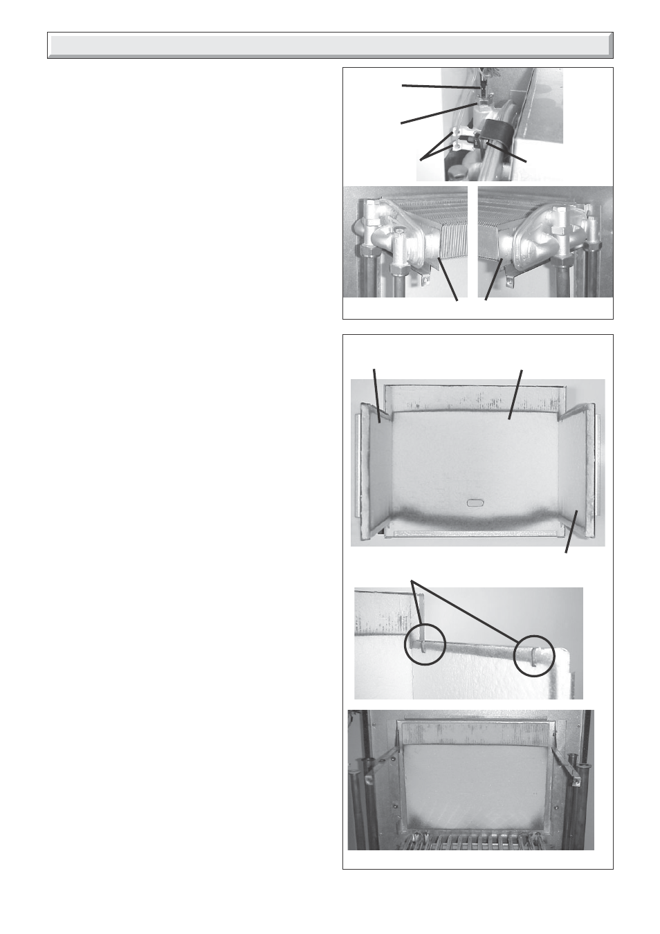
Diagram 18.8
OVERHEAT
THERMOSTAT
HEAT EXCHANGER
Diagram 18.9
9997
9988
CENTRAL
HEATING
THERMISTOR
➜
➜
➜
ELECTRICAL
LEADS
➜
ELECTRICAL
LEAD
9994
9995
18 Replacement of Parts
18.14 Heat exchanger, refer to diagram 18.8.
Before starting refer to the front of Section 18 Important
information.
• Remove the front panel, refer to Section 15.3.
• Lower the control panel, refer to Section 15.4.
• Remove the sealed chamber cover, refer to Section 15.5.
• Remove the combustion chamber cover, refer to Section
15.7.
• Drain down central heating water circuit and domestic hot
water cuircuit of the boiler only, refer to relevant part of
diagram 18.1.
• Remove the fan, refer to Section 15.10.
• Remove the flue hood, retained by two screws lift up and off.
• Remove the electrical leads from the overheat thermostat,
refer to diagram 18.8.
• Disconnect the four union nuts.
• Lift to remove the heat exchanger taking, care not to damage
the insulation.
18.15 Combustion chamber insulation, refer to
diagram 18.9.
Before starting refer to the front of Section 18 Important
information.
• Remove the front panel, refer to Section 15.3.
• Lower the control panel, refer to Section 15.4.
• Remove the sealed chamber cover, refer to Section 15.5.
• Remove the combustion chamber cover, refer to Section
15.7.
• Remove the heat exchanger, refer to Section 18.14.
• Carefully bend back side insulation retaining tabs, pull out side
and front insulation panels from combustion chamber.
• Tilt rear insulation panel forwards slide up and out.
• Fit replacement insulation.
18.16 Printed circuit board (PCB), refer to
diagram 18.10.
Before starting refer to the front of Section 18 Important
information.
• Remove the front panel, refer to Section 15.3.
• Lower the control panel, refer to Section 15.4.
• Gain access to rear of control panel.
• Undo and remove the two cover retaining screws. This will
disconnect the metal plate heat reflector.
• Hinge up the control panel cover and ease forwards from the
rear retaining lugs to gain access to PCB. Do not strain the
cables attached to the PCB. Note the routing of the cables.
• Carefully pull off electrical connections to PCB.
• Unclip and lift out PCB.
• Fit replacement PCB in reverse order to removal. Be careful
not to trap any of the cables.
Make sure that PCB connections are fully pushed onto
replacement PCB.
FRONT INSULATION
RIGHT HAND
INSULATION
LEFT HAND
INSULATION
RETAINING TABS
LEFT HAND SHOWN
9999
REAR INSULATION
10031