Fig. 7 fig. 8 – EZ-ACCESS TITA MODULAR ACCESS SYSTEM User Manual
Page 7
– 7 –
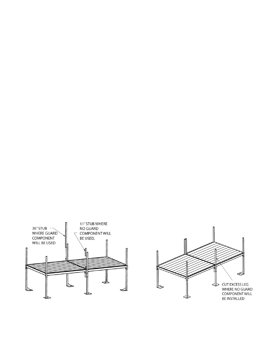
1.7.6 In all locations where there will be no guards or filler sections install the 1-1/2” square x 11”
long tube provided through the platform corner pocket and connector until it aligns with the
bottom of the connector and tighten all setscrews securely (FIG. 5).
1.7.7 At this point there will be one or more legs that extend above the platform deck and will not
be used to attach a guard, filler section or corner post. Mark these legs at the top of the
corner pocket and cut the leg off at or slightly below the mark (FIG. 8). Note: The
appearance and quality of the cut is not critical since these areas will be covered with a plate
in later steps. What is critical is that the leg not stick up past the deck far enough to interfere
with the plate when it is installed.
1.7.8 Additional platforms are added by repeating steps 1.7.4 thru 1.7.7 until the deck is complete.
There are, however, a few requirements that should be followed regardless of platform’s
position within the deck.
1.7.8.1 There should always be one leg and one “stub” in a dual platform connector. This
may require repositioning a connector from the way it was initially oriented (or
replacing a stub with a leg) depending on the configuration. Never use two “stubs”
without a leg in a dual platform connector.
1.7.8.2 Where four platforms come together, the two legs should be oriented so that they are
diagonally opposite from each other (FIG. 9).
1.7.8.3 Whenever possible, especially where four platforms come together, the dual platform
connector on one side of a platform should be oriented in the opposite direction from
the other side and the orientation should then be alternated as the deck is created
(FIG. 10).
1.7.8.4 Regardless of connector orientation, make sure there is a minimum of two legs
installed in each platform’s corner pockets (FIG. 11).
1.7.9 Once the deck is complete all areas where platforms connect that are not used to attach a
guard, filler section or corner post must be covered with a Corner Cover Plate (FIG. 12).
1.7.9.1 Use the corner cover plate provided to mark the location of the hole in the deck and
drill four holes between 0.129” and 0.133” dia. (#30 drill size).
1.7.9.2 Use the four 1/8” dia. rivets provided to attach the corner cover plate.
1.7.9.3 Use two cover plates where four platforms come together.
FIG. 7
FIG. 8