EZ-ACCESS TITA MODULAR ACCESS SYSTEM User Manual
Page 14
– 14 –
5.2
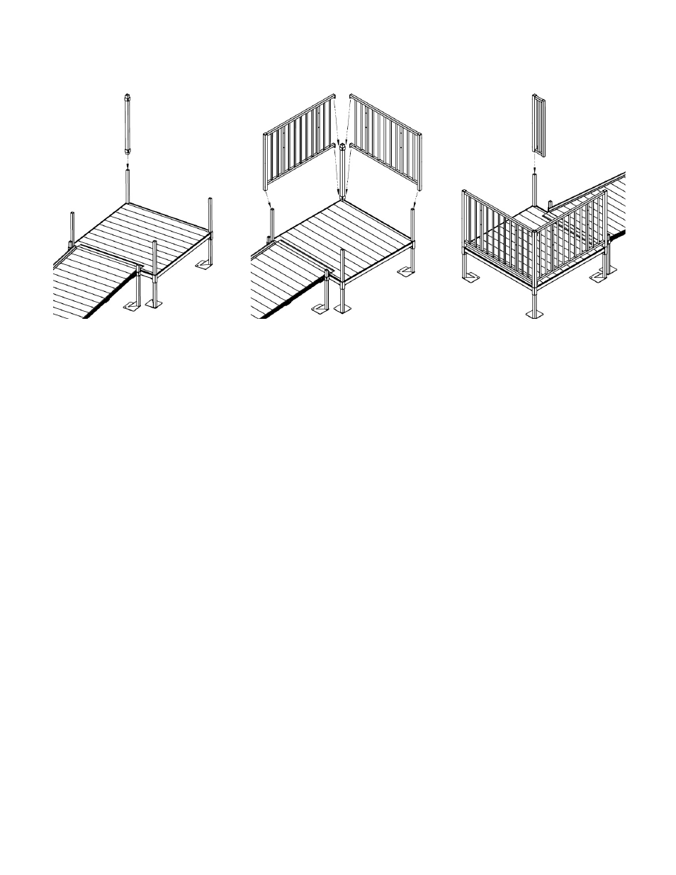
There are three basic platform arrangements: turn, turn-back, and straight through. Select
appropriate guardrail installation and assemble rails as shown in FIG. 22 through FIG. 28.
FIG. 22
FIG. 23
FIG. 24
5.3 If platform turns into a door at the top of the system:
5.3.1 Place one guard post over the support leg extending out of the platform corner pocket,
opposite both the door and ramp side (FIG. 22). Do not tighten. Note: Tab brackets
should be oriented toward the inside.
5.3.2 Place two 5 ft. guards over support legs protruding out of platform corner pockets
adjacent to guard post (FIG. 23) and engage tabs on guard section into tab brackets
on guard post. Do not tighten setscrews.
5.3.3 Place guard filler section over the remaining support leg with the tab brackets facing
the outside of the platform (FIG. 24).
5.3.4 Tighten lower two 3/8”-16 setscrews in each of the four vertical guardrail posts with
3/16” hex key wrench securely (FIG. 25).
5.4 If platforms are used to create a turnback:
5.4.1 Both platforms will use the same guard components as above except in mirror image (shown
in FIG. 26).
5.4.2 Tighten lower two 3/8”-16 setscrews in each of the four vertical guardrail posts with 3/16” hex
key wrench securely (FIG. 25).
5.5 If platform is used as a turn from one ramp to another (FIG. 27):
5.5.1 Place one guard post over support leg extending out of the platform corner pocket opposite
both ramps (tab brackets should be oriented toward the inside). Do not tighten.
5.5.2 Place two 5 ft. guards over support legs protruding out of platform corner pockets adjacent to
guard post.
5.5.3 Engage tabs on 5 ft. guard sections into tab brackets on the guard post, but do not tighten.
5.5.4 Place guard corner section over the remaining support leg.
5.5.5 Tighten lower two 3/8”-16 setscrews in each of the four vertical guardrail posts with 3/16” hex
key wrench securely (FIG. 25).
5.6 If platform is used as a straight through resting platform (FIG. 28):
5.6.1 Place two guard posts over protruding support legs on one end of the platform that a ramp is
joining. Note: The unused tab brackets should be oriented to the outside of the platform and
capped.
5.6.2 Place two 5 ft. platform guards two over support legs, making sure to engage tabs on
platform guards into tab brackets on guard posts.
5.6.3 Tighten the lower 3/8”-16 setscrews, two in each of the four vertical guardrail posts with 3/16”
hex key wrench securely (FIG 25).