E-Tech EH series User Manual
Page 7
13
12
2.2 Temperature of pumped fl uids
The pumped liquids must remain within certain
temperature limits:
• with EPDM seals: -15° to +110°C
• with VITON seals: -15° to +90°C
• with NBR seals: -15° to +80°C
3. INSTALLATION AND PREPARATION
3.1 Conditions of use
The horizontal electric pumps are multistage pumps
operating with clockwise rotation looking at the electric
pump from the motor fan.
• Pump not self-priming.
• Maximum density of the pumped liquid: 1.1 kg / dm³.
• Allowed voltage variation: ± 5% (single-phase voltage
220÷240V 50Hz, three-phase 380÷415V / 220÷240V
50Hz).
• Degree of protection: IP55.
• Sound pressure level lower than 70 dB (A).
• Dimensions and overall dimensions (See technical
catalog).
• Maximum ambient temperature: +40°C.
3.2 Minimum suction pressure
Check the characteristic curves of electric pumps to
evaluate the NPSH factor and avoid cavitation problems
(case in fi gure 1.B on page 4).
3.3 Maximum suction pressure
It is important to maintain the sum of input and output
pressure; this latter, with closed opening, shall always
be lower than the allowed maximum operating pressure
for the electric pump. However, the maximum operating
pressure shall never exceed 10bar (case in Figure 1.A
on page 4).
3.4 Minimum
nominal
fl ow rate
The operation of the electric pump at a lower level
of nominal minimum allowed fl ow rate may result in
excessive overheating, which may damage the electric
pump.
m
The electric pump must never be operated with
the discharge valve closed.
4. ELECTRICAL CONNECTIONS
c
Before beginning to work on the electrical pump,
make sure that you have disconnected the
electricity from the power supply mains and that
it cannot be accidentally reconnected.
The installation of the electrical pump can involve a
certain amount of complexity. For this reason, it must be
performed by competent and authorized installers.
Legend fi gure 1 (see also p. 4):
1. Filter (maximum passage section of 1 mm)
2. Valve-fi lter (maximum passage section of 1 mm)
3. Gate valve
4. Manometer
5. Check Valve
6. Positive slope
7. Pipe anchoring elements
8. Storage container
There may be two important application cases:
• Case outlined in fi gure 1.A (see p. 4). System with pump
under head (positive head), be it a tank as shown in the
fi gure or the civil water supply network, the system must
provide protection in case of lack of water.
• Case outlined in fi gure 1.B (see p. 4): Plant with suction
pump.
4.1 Mounting
Install the pump in an accessible place, protected against
frost and as close as possible to the water collection
point.
The electric pump must be fi rmly attached to the base by
means of bolts.
Allow enough space around the electric pump to allow
use and maintenance operations, as well as any possible
collection of hazardous liquids or liquids that need to be
drained at a temperature above 60 °C. In any case, make
sure that there is a clearance of at least 100 mm from the
cooling fan.
To avoid unnecessary stress to the pump body install
support brackets (see Figure 1, note 7 on page 4) to
support the inlet and outlet pipe.
To avoid air pockets harmful to the electric pump
operation, provide for an inclination of the inlet pipes of at
least 2% (see Figure 1, note 6 on page 4.)
Protect the pump from any water hammer through a check
valve placed in the delivery pipe. Install a shutoff valve
upstream and downstream of the pump so as to allow its
isolation in case of maintenance and disassembly.
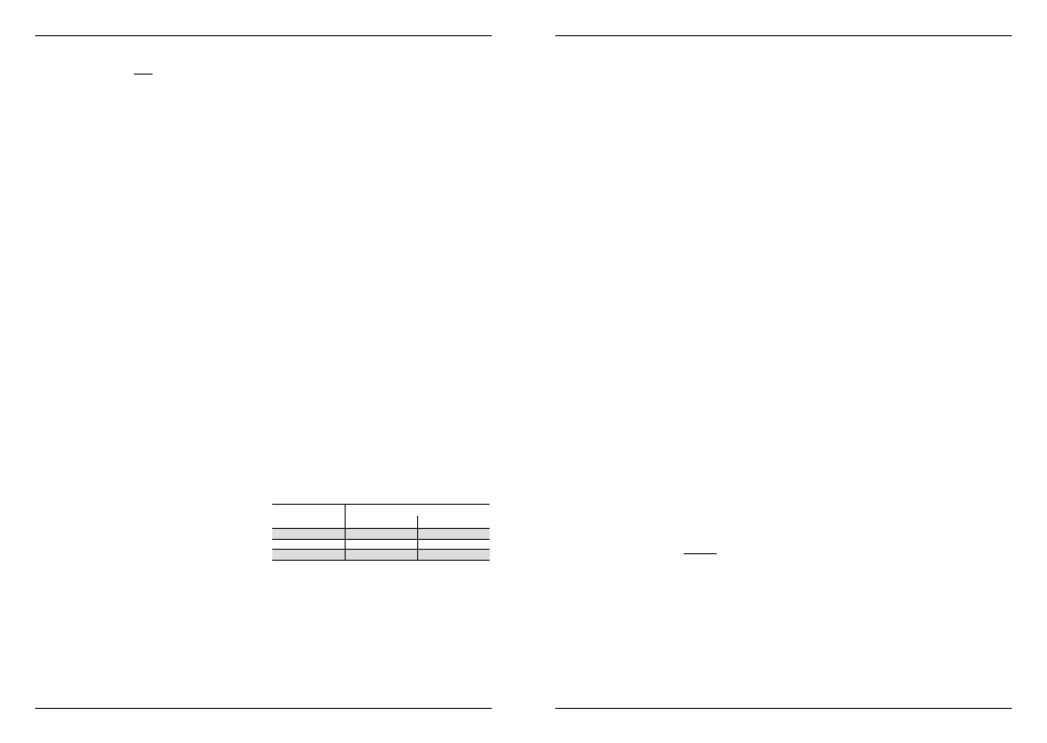
The diameter of inlet pipes should never be less than the
diameter of the inlet opening.
For the diameter of the connection piping refer to the
following table:
Pump type
DN threaded sleeves
Suction
Delivery
3
1" ¼
1"
5
1" ¼
1"
9
1" ½
1" ¼
4.2 Electrical
connections
c
Before beginning to work on the electrical pump,
make sure that you have disconnected the
electricity from the power supply mains and that
it cannot be accidentally reconnected.
Connections must only be performed by an authorized
electrician in compliance with law in force.
c
Verify that the data on the name plate match
the nominal values for the power line. Make
the connection after verifying the existence of
a working grounding circuit. It is the installer’s
responsibility to perform the connection in
compliance with regulations in force in the
country of installation.
Connect the electric pump by means of an external
network switch having a minimum distance between the
contacts of at least 3 mm on all poles.
Connect the wires to the motor according to the diagram
shown inside the terminal cover.
• For single-phase versions see Figure 3.A on page 5.
• For three-phase versions see Figure 3.B on page 5.
c
Use cable complying with the regulations,
equipped with ground wire (3 conductors for
single-phase versions and 4 conductors for
three phase versions)
c
Avoid any way contact between the electric
cables and the pipes or other parts of the pump;
carefully insulate the cables from moisture.
The single-phase versions are accompanied by internal
capacitor to the output variable.
For all single-phase versions, the engine is protected
against overloads by means of a thermal device (overload
cut-out) inserted into the winding.
The three-phase versions require external protection
(quick disconnect magnetic overload cut-out) with a
tripping time set to:
• Less than 10 seconds with 5 times I
N
• Less than 10 minutes with 1.5 times I
N
I
N
= maximum current value indicated on the rating plate.
The pump must supplied through a residual current
device (RCD) with a rated residual operating current
≤30mA.
4.3 Checking the direction of rotation
After connecting the power supply, the direction of
rotation can be inverted in the 3-phase versions; in this
case, performance will be signifi cantly lower than the
nominal values. To verify a correct connection, proceed
as follows:
1) Start the pump, check that the direction of rotation is
as indicated by the arrow. Warning! If this operation is
made under dry conditions, it shall not last more than
a few seconds.
2) To correct the rotation is suffi cient to invert the two
phases.
c
Do not fail to connect the grounding.
5. COMMISSIONING
CAUTION: The pump should NOT be started without
having been fi lled fi rst. Its dry use may irreparably
damage the mechanical seal.
5.1 Filling
5.1.1 Electric pump being charged (see fi gure
1.A and fi gure 2.A on page 4 and 5)
1. Close the gate valves on the delivery side of the
electric pump so as not to let the fl uid that you are
using for fi lling the electric pump circulate in the
circuit.
2. Remove the fi lling cap (see Figure 2.A on page 5).
3. Open the gate valve placed on the suction side of the
pump to drain the fl uid present in the pump. Make
sure that the difference in level between the pump
and the head is such as to ensure a complete fi lling of
the pump.
4. When there is a homogenous fl ow from the fi lling
hole, place the fi lling cap carefully back to its position.
5. Start the pump and check, only on three-phase
versions, that the direction of rotation is as indicated
by the arrow. To correct the direction of rotation is
suffi cient to invert the two phases.
6. Slowly open the valve gate on the delivery side till its
stroke end.
m
Pay particular attention to point 3 - when the
pump is fi lled with hot liquids or hazardous
liquids, fl uid leaking from the drain cap could hit
more people; make sure to be in a safe position
during this operation. In this case, close the
gate valve after the release of a constant fl ow
of liquid from the cap before closing it in order to
avoid contact with the liquid.
m
Depending on the temperature of the pumped
liquid, the electric pump surfaces can reach high
temperatures. If deemed necessary, provide for
guards to prevent accidental contact.
5.1.2
Pump during suction operations (see
fi gure 1.B 2.A fi gures and on page 4 and
5)
1. Close the gate valves on the delivery side of the
electric pump so as not to let the fl uid that you are
using for fi lling the electric pump circulate in the circuit
and open the gate valve on the suction side.
2. Remove the fi lling cap (see Figure 2.A on page 5).
3. Fill the pump as outlined in fi gure 2.A until the fl uid
comes out from the fi lling hole.
4. Close the fi lling cap carefully.
5. Start the electric pump and check, only in three-phase
versions, that the direction of rotation is as indicated
by the arrow. To correct the direction of rotation is
suffi cient to invert the two phases.
7. Slowly open the gate valve on the delivery side till its
stoke end.
m
Depending on the temperature of the pumped
liquid, the electric pump surfaces can reach high
temperatures. If deemed necessary, provide for
guards to prevent accidental contact.