3 calibration for co, o, Hc and co, Gas channels) – ENMET MEDAIR 2200 User Manual
Page 18
M
ED
A
IR
2200
ENMET Corporation
15
5.3 Calibration for CO, O
2,
HC and CO
2
(Gas Channels)
Calibration is the process of setting the instrument up to read accurately when exposed to a target gas. This is a two
step process. A Low Calibration sets clean air reference point and the High Calibration function sets the sensitivity of
the instrument.
Calibration equipment is available from
ENMET
Corporation to calibrate the
M
ED
A
IR
2200
. A list of needed
material is in Section 7.0. A calibration adapter will have a fitting for the gas cylinder on one side, and a quick-
disconnect to attach to the instrument on the other.
You may exit the calibration section, at any time, by pressing and holding the
OPTION
switch for 3 seconds, if entering
calibration section by mistake or calibration gas is not available.
Wait 24 hours after initially supplying air and power to the
M
ED
A
IR
2200
sensor before initial calibration. It is not
necessary to open the Front Panel to make adjustment. The calibration functions are operated through the
OPTION
and
SELECT
switches on the front panel.
After entering a valid password to maintenance menu, see Section 5.2.1, the calibration section is the first menu
section; enter by pressing the
SELECT
switch.
Supply sensor with clean air for LowCal/ZeroCal setting and apply calibration gas for HiCal/SpanGas setting.
Press the
SELECT
switch "
Calibration Select XX
" is displayed.
XX
= the gas to be calibrated
Press the
OPTION
switch, if needed, to change to the gas to be calibrated.
Press the
SELECT
switch, the gas & current reading are displayed in upper portion of display. The mV reading &
"
LowCal 0
" is displayed in the lower portion of display. This is the LowCal setting, usually zero, clean air must
be supplied to the sensor. This reading needs to be at or near zero. If it is not then a cylinder of clean 20.9 air
should be used. See Figure 7 if this is required.
Press the
SELECT
switch, that moves the cursor one digit to the right when the last digit is accepted the display
will move to "
HiCal xx
" gas calibration.
xx
= the level of gas to be used for calibration. The mV reading is
shown in the upper right hand corner of the display.
Apply calibration gas to sensor. See Figure 7. After about 1 minute and mV reading has stabilized.
Press the
SELECT
switch, that moves the cursor one digit to the right, when the last digit is accepted and the
calibration is successful the display will momentarily show Cal OK then slope and off set readings, before
returning to the Calibration Menu
Repeat above steps for each channel to be calibrated.
To continue on too next section Press the
OPTION
switch.
Press
OPTION
switch until “Exit maint menu” appears and then press
SELECT
switch to return the instrument to the
Operational Display
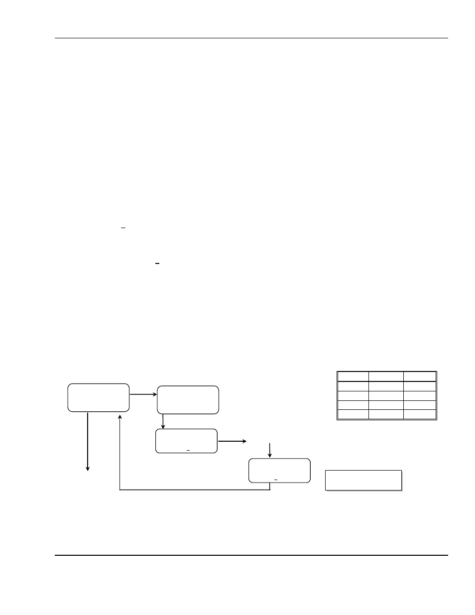
Example: Full Calibration Flow Chart, for CO
From Valid Password Entry
N
OTE
:
The dew point sensor/probe can not be calibrated in the field and should be replaced every two years.
O
S
S
Calibration
Select (Gas)
MAINTENANCE MENU
Calibration
O
Press
O
PTION
until the gas to be
Calibrated is displayed
CO: XX
11
LowCal: 0000
S each digit
CO: XX
14
HiCal: 0000
S each digit
Default Calibration Points
Gas
LowCal HiCal
CO
0
20
O2
N/A
20.9
CO
2
0
1000
HC
0
10
O = Press Option
S = Press Select