Advanced troubleshooting, Elenco, Adult supervision recommended) – Elenco XP&trade User Manual
Page 9
Advanced Troubleshooting
(Adult supervision recommended)
-8-
ELENCO
®
150 Carpenter Avenue
Wheeling, IL 60090 U.S.A.
Phone: (847) 541-3800
Fax: (847) 520-0085
e-mail: [email protected]
Website: www.elenco.com
You may order additional /
replacement parts at:
www.snapcircuits.net
ELENCO
®
is not responsible for parts
damaged due to incorrect wiring.
If you suspect you have damaged parts,
you can follow this procedure to
systematically determine which ones need
replacing:
(Note: Some of these tests connect an LED
directly across the batteries without another
component to limit the current. Normally this
might damage the LED, however Snap Circuits
®
LEDs have internal resistors added to protect
them incorrect wiring, and will not be damaged.)
1.
LEDs (D1 & D2), motor (M1), speaker
(SP), and battery holder
(B3):
Place
batteries in holder. Place one of the LEDs
directly across the battery holder (LED + to
battery +), it should light. Do the same for
the motor, it should spin. “Tap” the speaker
across the battery holder contacts, you
should hear static as it touches. If none
work, then replace your batteries and
repeat. If still bad, then the battery holder is
damaged.
2.
Jumper wires:
Use this mini-
circuit to test
each jumper
wire, the LED
should light.
3.
Snap wires:
Use this mini-circuit to test
each of the snap wires, one at a time. The
LED should light.
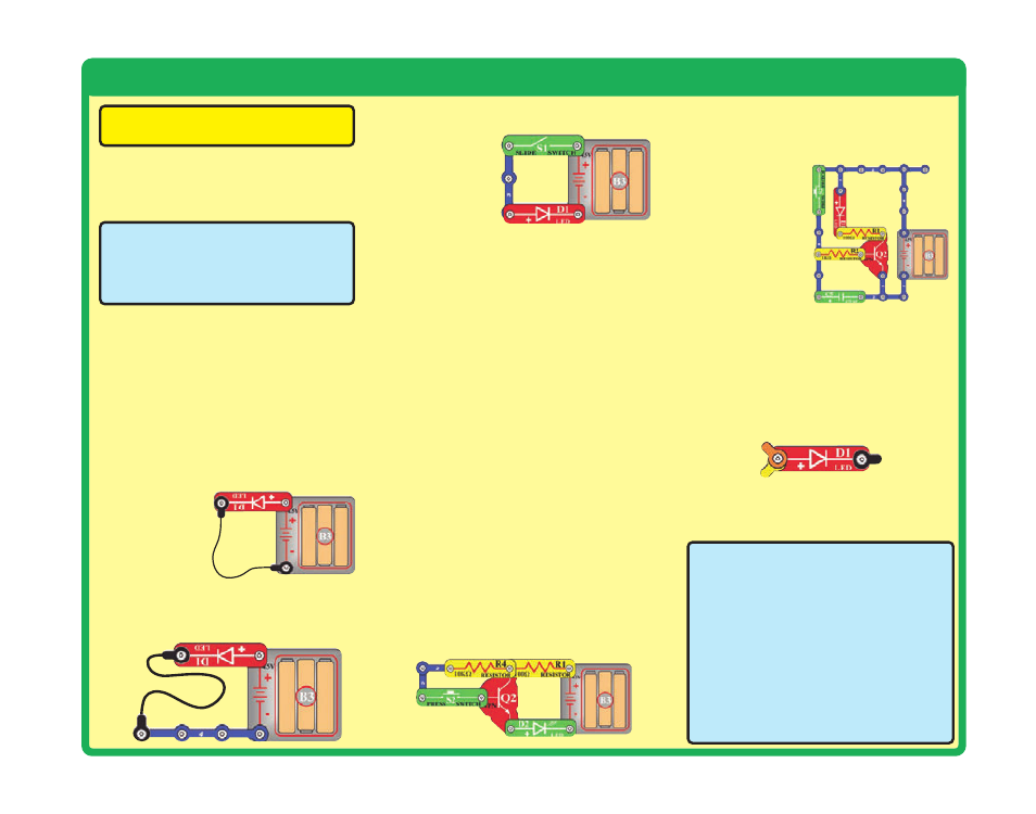
4.
Slide switch (S1) and Press switch (S2):
Use this mini-circuit; if the LED doesn’t light
then the slide
switch is bad.
Replace the
slide switch
with the press
switch to test it.
5.
100
Ω
(R1), 1k
Ω
(R2), and 10k
Ω
(R4)
resistors:
Use the mini-circuit from test 4
but replace the switch with the 100
Ω
resistor
(R1); the LED will be bright if the resistor is
good. Next use the 1k
Ω
and 10k
Ω
resistors
in place of the 100
Ω
resistor; the LED
should be dimmer but still light.
6.
Microphone (X1) and Photoresistor (RP):
Use the mini-circuit from test 4 but replace
the switch with the microphone (X1, + on
right); if blowing into the microphone does
not change the LED brightness then the
microphone is bad. Replace the microphone
with the photoresistor. Waving your hand
over the photoresistor (changing the light
that shines on it) should change the
brightness of the LED or the photoresistor
is bad.
7.
Adjustable resistor (RV):
Build Project
#A16, the resistor control lever should turn
the LED (D1) on and off; otherwise it is bad.
8.
NPN transistor (Q2):
Build the mini-circuit
shown here. The LED (D2) should only be
on if the press switch (S2) is pressed. If
otherwise, then the NPN is damaged.
9.
470
μ
F capacitor (C5) and 100k
Ω
resistor (R5):
Build the mini-circuit shown
here. When you press the switch, the LED
should be bright but then slowly get dim,
otherwise the
capacitor is bad.
Replace the 1k
Ω
resistor (R2)
with the 100k
Ω
resistor (R5); the
LED should stay
on much longer
or R5 is bad.
10.
Programming cable:
Connect the cable
to the red LED (D1), orange and yellow
wires to (+) and black wire to the other
side. Run the AXEpad for Snap Circuits®
XP software. Open a terminal (press F8).
Type something into the output buffer and
press Send. The red LED should flash and
what you typed should appear in the input
buffer.
11.
Microcontroller (U21):
Use project B27
(Test the Microcontroller).