Project #277, Space war sounds with led project #276, Led fan rotation indicator – Elenco Projects 102-305 User Manual
Page 64
-63-
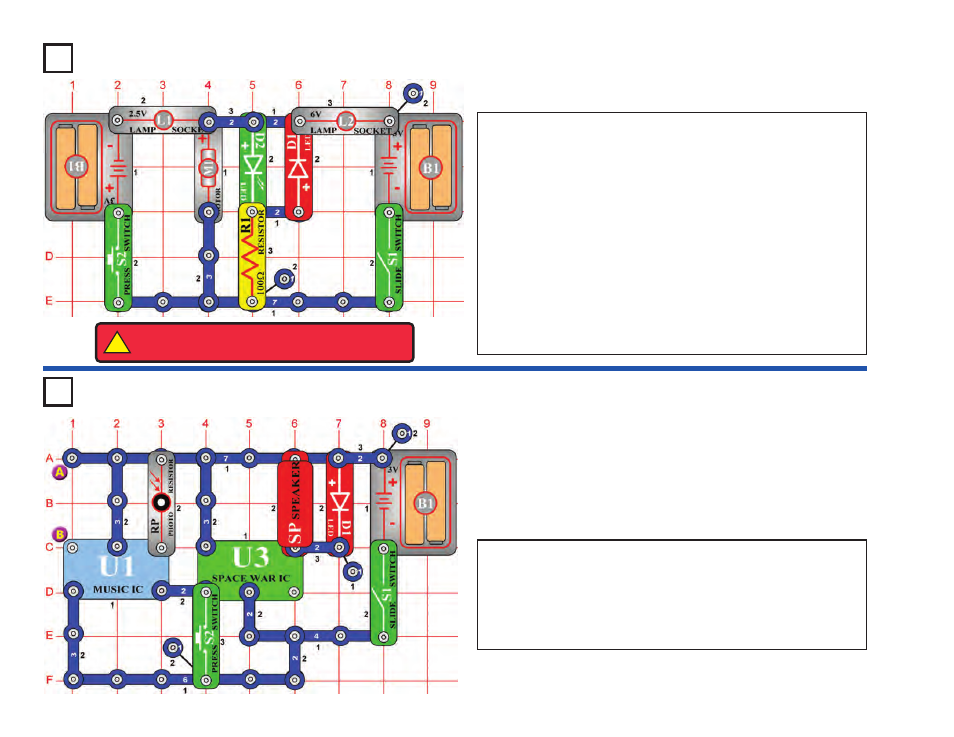
Project #277
OBJECTIVE:
To build a circuit that uses a programmed sound
integrated circuit (IC).
Space War Sounds
with LED
Project #276
OBJECTIVE: To build an LED fan rotation indicator.
Do not place the fan onto the motor (M1). Turn the slide switch (S1) on.
The motor rotates clockwise, and the green LED (D2) lights. When you
connect the positive (+) side of the battery (B1) to the positive (+) side
of the motor, it spins clockwise. Turn the slide switch off and press the
press switch (S2). Now the fan spins the other way and the red LED
(D1) lights. The positive (+) side of the battery is connected to the
negative (–) side of the motor. The polarity on the motor determines
which way it rotates.
Now place the fan on the motor, and turn on S1 or S2 (not both). Now
one of the lamps (L1 or L2) lights as the motor spins, but the LED is
dim.
The motor needs a lot of current to spin the fan, but only a little current
to spin without it. In this circuit, a lamp lights when the motor current is
high, and an LED lights when the motor current is low. The lamps also
prevent a short circuit if both switches are on.
LED Fan Rotation Indicator
Build the circuit shown on the left, which uses the space war integrated
circuit (U3). Turn the slide switch (S1) on. A space war sound plays,
and the LED (D1) flashes. If there is no light on the photoresistor (RP)
then the sound will stop after a while.
You also make sounds by pressing the press switch (S2). See how
many sounds are programmed into the space war sound IC.
Visit www.snapcircuits.net or page 74 to learn about Snap Circuits
®
upgrade kits, which have more parts and circuits.
!
WARNING:
Moving parts. Do not touch the fan or
motor during operation. Do not lean over the motor.