More, About your snap circuits, Parts – Elenco Projects 102-305 User Manual
Page 4
-3-
(Part designs are subject to change without notice).
Note: There is additional information in your other project manual.
The green
LED (D2)
works the same as the red LED (D1) and the
6V lamp (L2)
works the same as the 2.5V lamp; these are
described in the projects 1-101 manual.
Resistors “resist” the flow of electricity and are used to control or
limit the electricity in a circuit. Snap Circuits
®
includes
100
Ω
(R1),
1K
Ω
(R2), 5.1K
Ω
(R3), 10K
Ω
(R4), and 100K
Ω
(R5) resistors
(“K”
symbolizes 1,000, so R3 is really 5,100
Ω
). Materials like metal
have very low resistance (<1
Ω
) and are called conductors, while
materials like paper, plastic, and air have near-infinite resistance
and are called insulators.
The
adjustable resistor (RV)
is a 50K
Ω
resistor but with a center
tap that can be adjusted between 0
Ω
and 50K
Ω
. At the 0
Ω
setting,
the current must be limited by the other components in the circuit.
The
microphone (X1)
is actually a resistor that changes in value
when changes in air pressure (sounds) apply pressure to its
surface. Its resistance typically varies from around 1K
Ω
in silence
to around 10K
Ω
when you blow on it.
Capacitors are components that can store electrical pressure
(voltage) for periods of time, higher values have more storage.
Because of this storage ability they block unchanging voltage
signals and pass fast changing voltages. Capacitors are used for
filtering and oscillation circuits. Snap Circuits
®
includes
0.02
μ
F
(C1), 0.1
μ
F (C2), 10
μ
F (C3), 10
μ
F (C4), 470
μ
F (C5) capacitors,
and a variable capacitor (CV).
The variable capacitor can be
adjusted from .00004 to .00022
μ
F and is used in high frequency
radio circuits for tuning. The whistle chip (WC) also acts like a
0.02
μ
F capacitor in addition to its sound properties.
The
antenna (A1)
contains a coil of wire wrapped around an iron
bar. Although it has magnetic effects similar to those in the motor,
those effects are tiny and may be ignored except at high
frequencies (like in AM radio). Its magnetic properties allow it to
concentrate radio signals for reception. At lower frequencies the
antenna acts like an ordinary wire.
The
PNP (Q1) and NPN (Q2) transistors
are components that use
a small electric current to control a large current, and are used in
switching, amplifier, and buffering applications. They are easy to
miniaturize, and are the main building blocks of integrated circuits
including the microprocessor and memory circuits in computers.
Projects #124-125 and #128-133 demonstrate their properties. A
high current may damage a transistor, so the current must be
limited by other components in the circuit.
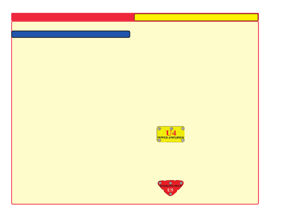
The
power amplifier IC (U4)
is a module containing an integrated
circuit amplifier and supporting components that are always
needed with it. A description of it is given here for those interested:
MORE
About Your Snap Circuits
®
Parts
The
high frequency IC (U5)
is a specialized amplifier used only in
high frequency radio circuits. A description of it is given here for
those interested:
INP
FIL
(+)
OUT
(–)
Power Amplifier IC:
(+) - power from batteries
(–) - power return to batteries
FIL - filtered power from batteries
INP - input connection
OUT - output connection
See project #242 for example of
connections.
High Frequency IC:
INP - input connection (2 points
are same)
OUT - output connection
(–) power return to batteries
See project #242 for example of
connections.
INP
INP
(–)
OUT
Our Student Guides give much more information about your parts along with a complete lesson
in basic electronics. See www.snapcircuits.net/learn.htm or page 74 for more information.