Project #172 red & green control, Project #173 current controllers, Project #174 current equalizing – Elenco Projects 102-305 User Manual
Page 29: Project #175 battery polarity tester
-28-
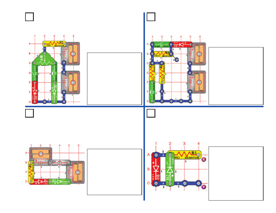
Project #172
Red & Green Control
OBJECTIVE: To demonstrate
how the adjustable resistor
works.
Project #173
Current Controllers
Turn on the circuit using the slide
switch (S1) and/or the press
switch (S2) and move the
adjustable resistor’s (RV) control
lever around to adjust the
brightness of the LED’s (D1 &
D2). When the adjustable resistor
is set to one side, that side will
have low resistance and its LED
will be bright (assuming the
switch on that side is ON) while
the other LED will be dim or OFF.
OBJECTIVE: To compare
types of circuits.
Build the circuit and turn on the slide
switch (S1), the LED (D1) will be lit.
To increase the LED brightness, turn
on the press switch (S2). To
decrease the LED brightness, turn
off the slide switch.
With the slide switch on, the 5.1K
Ω
resistor (R3) controls the current.
Turning on the press switch places
the 1K
Ω
resistor (R2) in parallel with
it to decrease the total circuit
resistance. Turning off the slide
switch places the 10K
Ω
resistor (R4)
in series with R2/R3 to increase the
total resistance.
Project #174
Current Equalizing
OBJECTIVE: To compare
types of circuits.
Project #175
Battery Polarity Tester
In this circuit the LED’s (D1 &
D2) will have the same
brightness, but the lamp (L1) will
be off. When connected in
series, all components will have
equal electric current through
them. The lamp is off because it
requires a higher current
through the circuit to turn on
than the LED’s do.
OBJECTIVE: To test the
polarity of a battery.
Use this circuit to check the
polarity of a battery. Connect
your battery to X & Y on the
drawing using the jumper cables
(your 3V battery pack (B1) can
also be snapped on directly
instead). If the positive (+) side
of your battery is connected to
X, then the red LED (D1) will be
on, if the negative (–) side is
connected to X then the green
LED (D2) will be on.