Project #269, Noise-activated burglar alarm – Elenco Projects 102-305 User Manual
Page 61
-60-
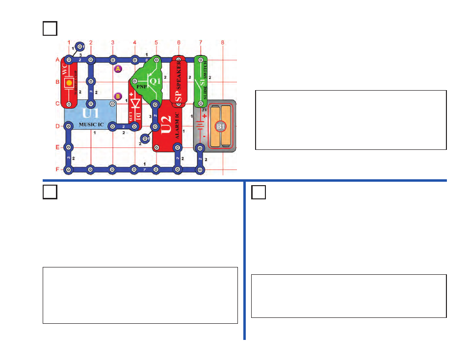
Project #269
OBJECTIVE: To build a noise activated alarm.
Noise-Activated
Burglar Alarm
OBJECTIVE: To b
uild a motor-activated burglar alarm.
OBJECTIVE: To b
uild a light-activated burglar alarm.
Use the circuit from project #269 shown above.
Replace the whistle chip (WC) with the motor (M1). Wind a piece of
string around the axis of the motor so when you pull it the axes spins.
Connect the other end of the string to a door or window. Turn the slide
switch (S1) on and wait for the sound to stop. If a thief comes in through
the door or window the string pulls and the axes spins. This will activate
the sound.
Project #270
Motor-Activated
Burglar Alarm
Project #271
Light-Activated
Burglar Alarm
Turn the slide switch (S1) on and wait for the sound to stop. Place the
circuit into a room you want guarded. If a thief comes into the room
and makes a loud noise, the speaker (SP) will sound again.
If you find that the sound does not turn off, then vibrations created by
the speaker may be activating the whistle chip. Set the speaker on the
table near the circuit and connect it to the same locations using the
jumper wires to prevent this.
Use the circuit from project #269 shown above.
Connect a photoresistor (RP) across points A & B and cover it or turn
off the lights. Turn the slide switch (S1) on and wait for the sound to
stop. At night, when the thief comes in and turns on the light, the
speaker (SP) makes the sound of a machine gun.
Visit www.snapcircuits.net or page 74 to learn about more Snap Circuits
®
products to add to your collection.