Project #202, Flooding alarm project #199 pitch, Project 201 pitch (iii) – Elenco Projects 102-305 User Manual
Page 36: Project 200 pitch (ii)
-35-
Project 201
Pitch (III)
OBJECTIVE:
See project #199.
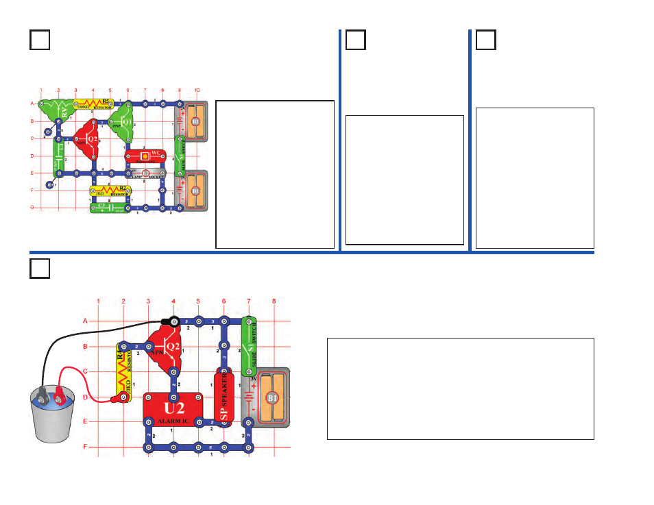
Project #202
OBJECTIVE: To sound an alarm when water is detected.
Flooding Alarm
Project #199
Pitch
OBJECTIVE: To show how
to change the pitch of a
sound.
Project 200
Pitch (II)
OBJECTIVE:
See project #199.
Remove the 0.1
μ
F (C2) capacitor
and replace the 100k
Ω
resistor
(R5) wth the photoresistor (RP).
Wave your hand up and down
over the photoresistor to change
the sound. Changing the light on
the photoresistor changes the
circuit resistance just like varying
the adjustable resistance does.
Note: If you have the adjustable
resistor (RV) set to the right and
light shining on the photoresistor,
then you may not get any sound
because the total resistance is too
low for the circuit to operate.
Build the circuit on the left, turn
it on, and vary the adjustable
resistor (RV). The
frequency or
pitch of the sound is changed.
Pitch is the musical profession’s
word for frequency. If you’ve
had music lessons, you may
remember the music scale
using chords such as A3, F5,
and D2 to express the
pitch of a
sound. Electronics prefers the
term
frequency, as in when you
adjust the frequency on your
radio.
Build the circuit on the left and connect the two (2) jumpers to it, place
the loose ends of the jumpers into an empty cup (without them
touching each other). Turn on the slide switch (S1) - nothing happens.
This circuit is designed to detect water and there is none in the cup.
Add some water to the cup - an alarm sounds!
You can use longer jumper wires and hang them near your basement
floor or next to your sump pump to give a warning if your basement is
being flooded. Note that if the loose jumper ends accidentally touch
then you will have a false alarm.
Since we’ve seen we can
adjust the frequency by
varying the resistance in the
adjustable resistor, are there
other ways to change
frequency? You can also
change frequency by
changing the capacitance of
the circuit. Place the 0.1
μ
F
capacitor (C2) on top of the
0.02
μ
F capacitor (C1); notice
how the sound has changed.