Input clock frequency and timer accuracy, Fixed timers, Scaled timers – Echelon Neuron C User Manual
Page 48
36
Focusing on a Single Device
Neuron Chip
IO_8
IO_9
IO_2
+5V
C4
.01 F
470
R10
3 Digit LED Display
Multi-Character
LED Display Driver
Vdd
CLOCK
DATA IN
DATA OUT
~ENABLE
RX
Vss
3
11
12
18
10
8
14
7
6
5
4
2
1
20
19
9
13
15
16
17
A
B
C
D
E
F
G
H
BANK 1
BANK 2
BANK 3
BANK 4
BANK 5
U3
MC14489
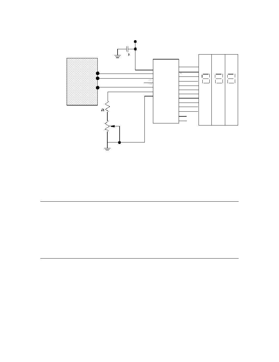
Figure 4. Neurowire Connection to a Display
Note that the figure does not show pull-up resistors for the IO_2, IO_8, or IO_9
pins; for a Series 3100 device, you can use the #pragma enable_io_pullups
directive to add pull-ups to these pins; for a Series 5000 device, you need to add
external pull-up resistors for the pins.
Input Clock Frequency and Timer Accuracy
Depending on the manufacturer and version, the Neuron Chip and Smart
Transceiver system clock frequencies are 80 MHz, 40 MHz, 20 MHz, 10 MHz,
6.5536 MHz, 5 MHz, 2.5 MHz, 1.25 MHz, and 625 kHz. Certain timers listed
below are
fixed timers
; that is, they have the same absolute duration regardless
of the input clock selected. However, the slower the system clock, the less
accurate the timer.
Scaled timers
, also listed below, scale in proportion to the
input clock.
Fixed Timers
In general, timers discussed in this manual are of fixed duration unless noted
otherwise. The following timers are implemented in hardware and have periods
that are independent of the Neuron Chip or Smart Transceiver input clock
frequency. However, the accuracy of these timers is determined by the accuracy
and frequency of the input clock for the Neuron Chip or Smart Transceiver.
• Preemption mode timeout timer.
• Pulsecount input timer. Timer used to determine the counting interval
for the pulsecount input object. The interval is (223)/107 (approximately
0.8388608) seconds.