Echelon Neuron C User Manual
Page 175
Neuron C Programmer’s Guide
163
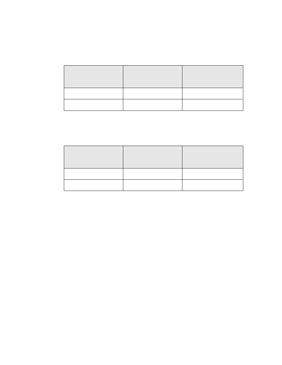
At the end of this preparation, the system firmware calls the interrupt dispatcher
within the Neuron C application. The dispatcher attempts to dispatch each
interrupt task, in source-code declaration order. For any given interrupt task,
the dispatcher adds latency, as shown in Table 11.
Table 11. Dispatcher Latency
Number of Interrupt
Tasks Defined within the
Application
Clock Cycles Required
for I/O or System Timer
Interrupts
Clock Cycles Required for
Timer/Counter Interrupts
1 7 10
More than 1
9
16
After the interrupt task completes, the system firmware performs a number of
clean-up steps. For any given interrupt task, the clean-up steps add latency, as
shown in Table 12. As the table shows, the clean-up steps apply only to
timer/counter interrupt tasks.
Table 12. Clean-Up Latency
Number of Interrupt
Tasks Defined within the
Application
Clock Cycles Required
for I/O or System Timer
Interrupts
Clock Cycles Required for
Timer/Counter Interrupts
1 0 63
More than 1
0
66
Figure 15 on page 164 summarizes how the system firmware and interrupt
dispatcher add latency to interrupt processing. In the figure, the numbers are
the clock cycles required for each step, as defined above. The numbers
N
0
,
N
1
,
and
N
2
represent the number of clock cycles required to run an interrupt task
itself.