Dillon Precision Super 1050 User Manual
Page 9
Remove the blue cap from the powder
die (#20320) and loosely clamp the
powder measure in position.
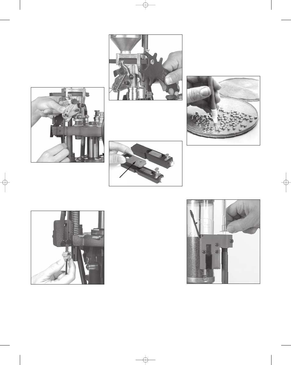
To install the powder bar return rod
(#13960) remove the blue wing nut
(#13799) and rod spring (#14033) from
the rod, then insert the bottom end
through the 3/8” eyebolt (#13089) that is
mounted on the left rear of the main
frame.
Next, using your thumb and index fin-
ger of your left hand, move the locklink
down and align the hole with the slot on
the bellcrank. Then, insert the rod
through the two holes and insert the
return rod clip (#13929). Fig. 17
Install the spring (#14033) and wing
nut (#13799) on the rod and screw the
wing nut up until you feel light tension
on the spring. Fig. 18 Tighten the pow-
der measure clamp screws (#14037).
You will notice an adjusting bolt on
the front of the powder bar. Counter-
clockwise reduces the powder charge,
clockwise increases the charge. Fig. 19
Your machine comes with two powder
bars. Fig. 20 One large (#20063) and
one small (#20062).
Index a sized and primed case under
the measure and operate the machine’s
handle. Turning the powder bar adjust-
ment bolt clockwise increases the pow-
der charge – counterclockwise turns
decreases the powder charge. By trial
and error, determine the correct weight
of your powder charge by using a pow-
der scale. Fig. 19
When the correct powder charge
had been set, cycle several cases
through the machine and check the
load with a scale.
Primer Magazine
Select the proper size primer pick-up
tube and fill it by placing the plastic tip
over loose primers and pressing down.
You will notice that the primer maga-
zines and primer pick-up tubes have dif-
ferent colored tips. They have been color
coded to help you identify size more
easily.
The color code is as follows:
Blue
Small Primer Magazine
Orifice
Red
Large Primer Magazine
Orifice
Yellow Small Primer Pick-up Tube
Green Large Primer Pick-up Tube
The shiny side of the primers should
be facing up. This is most easily accom-
plished by use of a primer flip tray.
Fig.
21 This quality cast metal flip tray is
available from Dillon Precision and is a
better choice than the smaller plastic
trays which are difficult to use and have
a tendency to warp.
Once you’ve filled the pick-up tube,
make sure the little retaining clip is in
place at the top of the tube. Fig. 22
Pivot the switch lever (#13864) away
from the Early Warning System housing
Fig. 17 - Install the return rod clip to secure
the powder bar return rod. See the schemat-
ic on page 31 for more details.
Fig. 18 - See the schematic on page 31 for
more details.
Fig. 19 - Clockwise turns of the powder bar
adjustment bolt increase the powder charge
while counterclockwise turns decrease the
powder charge.
Fig. 20 - Small powder bar (left), large pow-
der bar (right).
Spacer
Fig. 21 - All of the primers must be shiny
side up.
9
Fig. 22 - When installing primers into the
primer magazine, be sure the pick-up tube
centers itself before pulling the clip.
Super 1050, May 2007 5/21/07 12:00 PM Page 9