Dillon Precision Super 1050 User Manual
Page 15
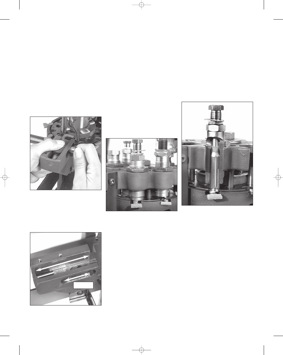
Casefeed Plunger Conversion
When changing calibers it may be
necessary to replace the casefeed
plunger (#13073*).
To do this, remove the clear casefeed
tube (#20533*) and pull out the colored
casefeed adapter (#13654*). The adapter
is taped for shipping purposes.
Remove the two housing screws
(#13815) and the casefeed adapter hous-
ing (#11006).
Place your hand on the plunger while
removing the roller bolt (#13333). This
will prevent the casefeed plunger and
spring from jumping out of the machine.
Fig. 45
Thoroughly clean the track and case-
feed parts with a solvent. Now very
lightly apply grease to the sides and
install the proper size casefeed plunger
(#13073*).
Fig. 46 Remember to
grease the roller (#13498) and the
roller track (
Fig. 46) and Loctite the
threads on the roller bolt (#13333).
Install the casefeed housing and insert
the proper size adapter (#13654*). The
casefeed tube (#20533*) should now be
inserted into the casefeed adapter
(#13654*). Note that the tube is marked
“up” on one end. Press this end into the
tube clip (#13859). See Troubleshooting
section for any adjustments.
Die Adjustments
Station 2 - To install the size/decap die
Warning: Never attempt to deprime
live primers, an explosion may result.
Move the toolhead down, by lowering
the handle all the way down.
Screw the sizing die into Station 2.
Continue to screw the die down until it
just touches the shellplate. Fig. 47
Tighten the die lock ring finger tight.
Now move the toolhead up by raising
the handle to its upright position.
Note: When loading .270 or .30-06
you need to raise the decap assembly so
that the hitch pin clip is a minimum of
1/8” above the silver lock ring as shown
in Fig. 47.
Place a case in the casefeed funnel.
Here, the case drops to the casefeed
plunger.
Cycle the handle. The casefeed cam
pushes the roller bushing back, dropping
the case into the slot of the plunger.
Cycle the handle. The case is inserted
into the shellplate.
Note: After raising the handle, insure
that you push the handle against its full
aft stop. This will insure that the
shellplate fully advanced to the next
station.
Note: When priming, pushing the
handle against its stop, will insure that
the primer is fully seated.
Again, move the toolhead down. The
case is now sized. If the case has a
spent primer, it will be deprimed.
Leave the toolhead in this position with
the case fully inserted in the die.
Fig.
48 This will ensure that the die
remains in alignment when tightening
the lock ring.
Using a 1" wrench to turn the lock
ring and a 7/8" wrench to hold the die
body, tighten the lock ring.
Station 3 - Adjustment of the Expander
Die
Install the expander die (caliber
specific) at Station 3. Place a case in
Station 2 and cycle the operating han-
dle once (sending the case to Station
3). Turn the expander die down until
you feel it make contact with the case
and cycle the operating handle. Make
adjustments in one-quarter turn incre-
ments until the desired expansion of
the case mouth is achieved. Tighten
the die lock ring.
A properly expanded case should
show a slight flare at the case mouth.
Fig. 49
15
Fig. 45 - The casefeed plunger and spring
are under tension. Hold them in place while
removing the roller bolt.
Fig. 46 - Be sure to lightly grease the sides
of the casefeed plunger track, casefeed
plunger and roller after cleaning.
roller track
Fig. 47 - Screw the size/decap die down
until it just touches the shellplate.
Fig. 48 - As the toolhead continues down,
it will reshape the case neck, shoulder
and body.
Super 1050, May 2007 5/21/07 12:00 PM Page 15