Dillon Precision Super 1050 User Manual
Page 13
of the pocket, once properly swaged,
the dents will no longer be visible. Fig.
31
Primer System Change Over
Instructions
The Super 1050 has been shipped to
you with either the large or small primer
system installed. To change the system
from large to small or vise versa, follow
these instructions:
Be sure all primers have been
removed from the primer system. Then
remove the Early Warning System and
the knurled cap. Then remove the primer
magazine (#22031 - large or #22030 -
small) and replace it with the new size
magazine. Be sure the key on the tip
(#14003 - large or #14024 - small) is in
the slot and the magazine is all the way
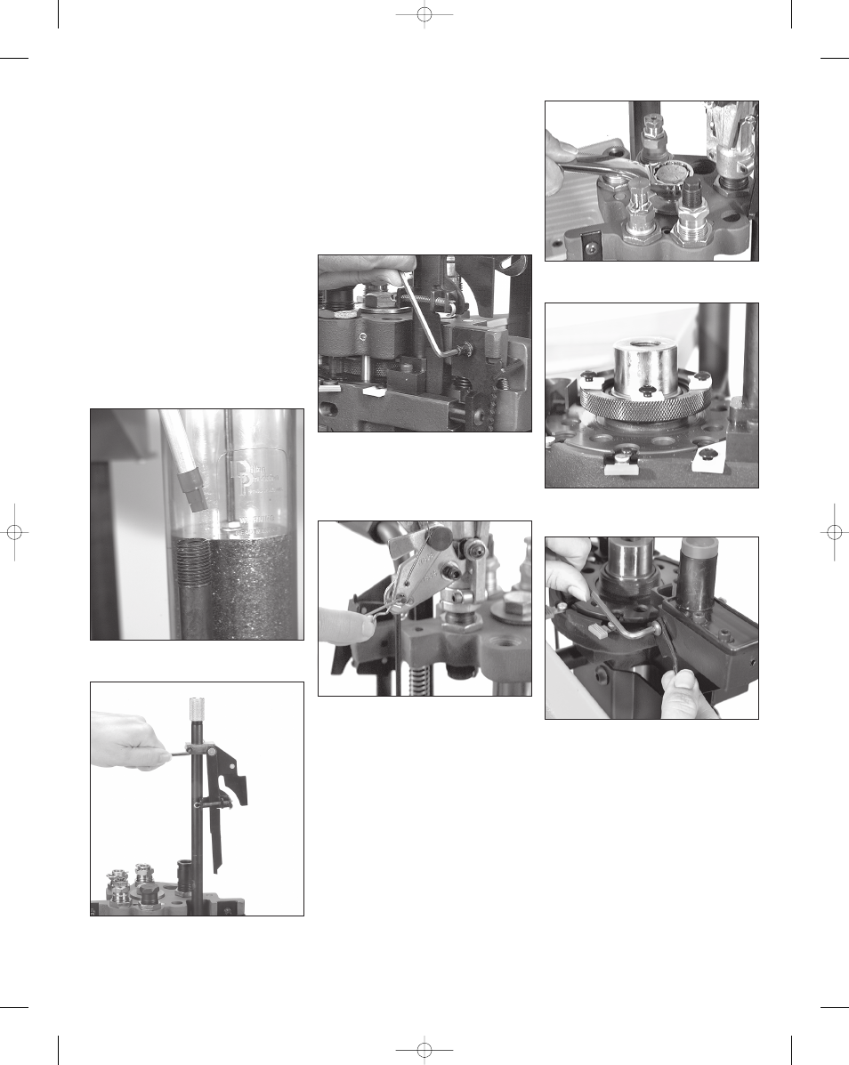
down in place. Fig. 32
Pull the operating handle to its down
position.
Loosen the lever arm bracket screw
(#14037) and slide the bracket assem-
bly up four inches and lock it in
place. Fig. 33
Raise the operating handle, remove
the two primer feed body screws
(#13363) and lift off the primer feed
body assembly (#20773).
Remove the toolhead ratchet (#11688)
by removing the bolt (#12486).
Fig. 34
Remove the powder bar return rod
(#13960) from the powder measure bellcrank
lock link assembly (#11234) by releasing the
return rod clip (#13929).
Fig. 35
Remove the casefeed tube (#20533*)
and place it on your bench. Remove
the toolhead.
Fig. 36 For more infor-
mation see the following section:
TOOLHEAD REMOVAL.
Now remove the shellplate lock nut
(#13425) by loosening the four locator
tab screws (#13895) about four full
turns. Fig. 37
Loosen the ejector tab screw
(#13896) and swing the ejector tab
(#13189) out of the way.
Fig. 38 Next,
slide the casefeed plunger (#13073*)
back and remove the shellplate.
Rotate the primer slide stop (#13108)
90˚. This will allow you to remove, and
replace, the primer slide (#20318 - large
or #20317 - small). Fig. 39
Next, remove the bushing (#13031 -
large or #13222 - small); spring
(#13858) and punch (#12849 - large or
#13307 - small) and replace them with
the parts for your new primer size.
Note that there is a specially designed
13
Fig. 32 - Note the shape of the key at the
base of the primer magazine tip.
Fig. 33 - Slide the bracket assembly up and
out of the way – retighten the lever arm
bracket screw to hold it in place.
Fig. 35 - After removing the clip and discon-
necting the rod, replace the clip in the rod
for safe-keeping.
Fig. 36 - To remove the toolhead unscrew
the toolhead bolt and remove.
Fig. 34: Remove the toolhead ratchet by first
removing the bolt (#12486). See the
Toolhead schematic on page 27
Fig. 37 - The four lock ring screws need only
be loosened about four turns to remove the
shellplate lock nut.
Fig. 38 - Loosen the screw and swing the
ejector tab out of the way.
Super 1050, May 2007 5/21/07 12:00 PM Page 13