Dillon Precision Super 1050 User Manual
Page 8
Step 5: Cycling the Machine
At this point your assembly should be
complete. Gently pull the operating han-
dle towards you, make a full stroke to
the bottom and up again. The shellplate
should be indexing and the primer slide
(#20318*) should function. The casefeed
plunger (#13073*) should travel forward
to the shellplate. Make sure that you
repeat this several times to gain an
understanding of the various functions of
the machine before you start reloading.
Fig. 13
Now plug in the casefeed motor and
activate the switch. The casefeed plate
should turn smoothly within the case-
feed bowl.
Assuming that all is well, proceed
with components.
Loading Components
Your Super 1050 is equipped with a
cartridge activated powder measure that
will dispense powder only when a car-
tridge is in Station 5.
It is important to understand that the
adjustable powder bar should reach the
end of its travel at the same time that
the handle reaches the bottom of its
stroke against the frame stop. Fig. 14
To achieve this adjustment, the die
body must be screwed up or down as
needed.
The powder die has already been
adjusted at the factory. An empty case
must be placed in the shellplate at
Station 5 in order to check this adjust-
ment. Note that the case used to adjust
the powder measure die must already be
sized.
NOTE: If you are adjusting for a
straight wall case, start your powder die
adjustment with the die obviously too
high and work down. This will avoid
over belling the case.
If you are adjusting a case with a
shoulder, such as a .223, do not turn the
die down too far or the shoulder will
buckle.
Use a reloading manual to determine
how much powder you need for a par-
ticular load and an accurate powder
scale to determine the weight. Caution:
While you do not have to use a Dillon
Precision powder scale, you should use
a scale of equal quality. Do not use
scales with plastic frames or “razor
blade” pivots. Quality scales have jew-
eled pivot points. Razor blade pivots
can dig into the frame of the scale and
give dangerously inaccurate readings.
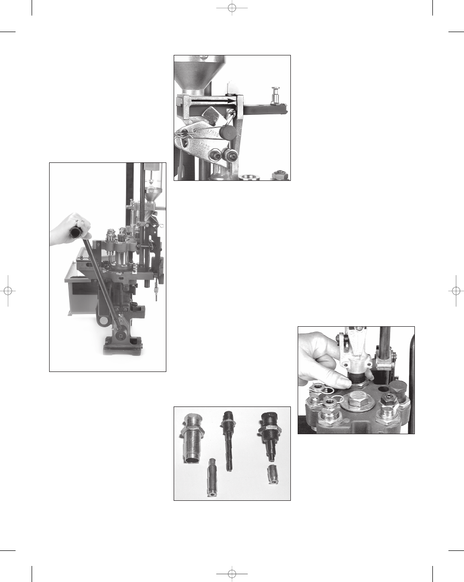
Powder Measure Adjustments
In Station 5 we adjust the powder
measure. It works like this: screw the
powder die into the toolhead and insert
the pistol powder funnel expander or a
rifle powder funnel with the grooved end
toward the top of the powder die. Fig.
15 The funnel should move freely in the
die, leaving a loose fit between the top
of the die and the powder measure col-
lar. This will enable you to adjust the die
to give you a bell on the mouth of your
pistol cases making it easier to start the
bullet.
On rifle cases, the die should be
adjusted so that the powder funnel will
contact the mouth of the case and then
fully actuate the powder bar. These
adjustments are accomplished with a
sized case in the shellplate and alter-
nately raising and lowing the operating
handle while adjusting the powder die.
When properly adjusted, the powder
bar will be moved to the end of its travel
by the cartridge case Fig. 14.
When you have determined that your
adjustments are correct, tighten the lock
ring (#14067).
Fig. 16
Powder Bar Return Rod Assembly
The purpose of the powder bar return
rod is to return the powder bar to its
closed position.
Fig. 13 - Cycle the handle several times to
observe the various functions.
Fig. 14 - This photo shows the powder bar at
the end of its travel.
Fig. 15 - Note the difference between the
rifle expander (center) and the pistol
expander (right).
Fig. 16 - Be sure to tighten the lock ring
when adjustments are completed.
8
Super 1050, May 2007 5/21/07 12:00 PM Page 8