Usb connectors (usb1 and usb2), Power and hdd led indicator (d1), 7 usb connectors (usb1 and usb2) – Axiomtek PICO841 User Manual
Page 37: 8 power and hdd led indicator (d1)
PICO841 Intel
®
Atom
TM
Processor E3845/E3827 Pico-ITX Board
AX93283 I/O Board
31
The pin assignments of CN10 are given as follows.
1 19
2 20
Note
Please gently insert CN9 and CN10 into CN2 and CN1 of PICO841.
3.5.7
USB Connectors (USB1 and USB2)
The board comes with two double-deck Universal Serial Bus (compliant with USB 2.0
(480Mbps)) connectors on the rear I/O which are for installing USB peripherals such as
keyboard, mouse, scanner, etc.
1 2 3 4
5 6 7 8
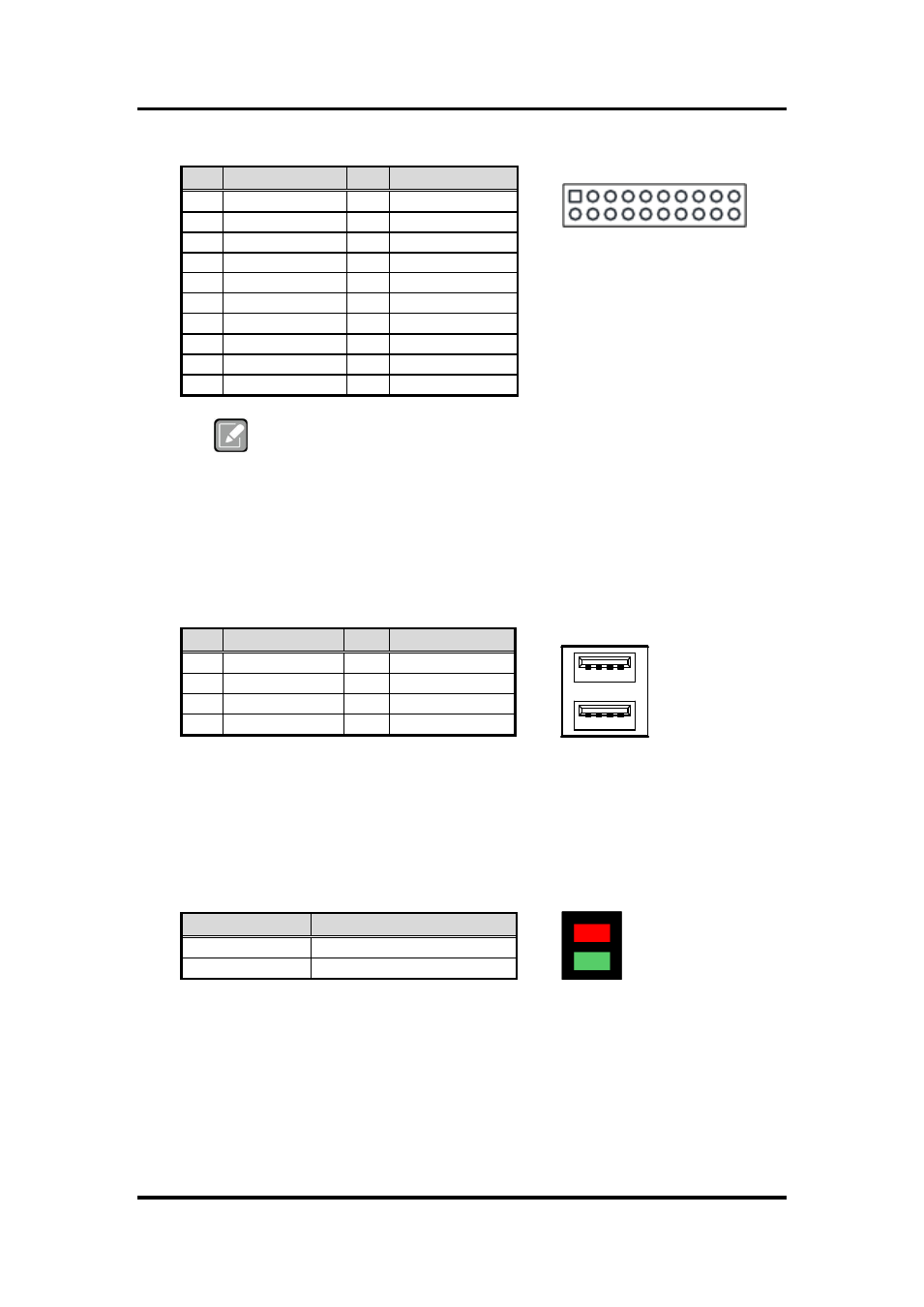
3.5.8
Power and HDD LED Indicator (D1)
The red LED is linked to Hard Disk Drive (HDD) activity signal. LED flashes every time
HDD is accessed.
The power LED (green) lights up and will remain steady while the system is powered on.
Pin Signal
Pin Signal
1
DCD2
2
DSR2
3
RXD2
4
RTS2
5
TXD2
6
CTS2
7
DTR2
8
RI2
9
GND
10
+5V
11
DCD1
12
DSR1
13
RXD1
14
RTS1
15
TXD1
16
CTS1
17
DTR1
18
RI1
19
GND
20
+5V
Pin Signal
Pin
Signal
1
+5V
5
+5V
2
USB1/3_DATA-
6
USB2/4_DATA-
3
USB1/3_DATA+
7
USB2/4_DATA+
4
GND
8
GND
LED Color
Description
Red
Hard disk drive activity
Green
Power on/off