Board to board connectors (cn1 and cn2), 1 board to board connectors (cn1 and cn2) – Axiomtek PICO841 User Manual
Page 21
PICO841 Intel
®
Atom
TM
Processor E3845/E3827 Pico-ITX Board
Board and Pin Assignments
15
2.5.1
Board to Board Connectors (CN1 and CN2)
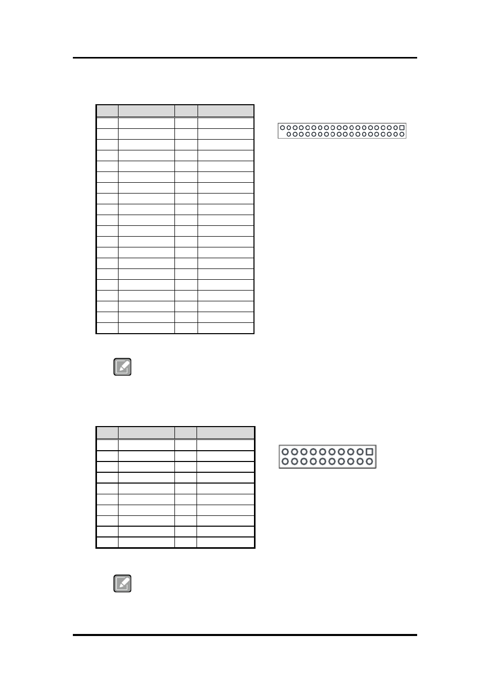
The pin assignments of CN1 are given as follows.
39 1
40 2
Note
During Windows
®
7 installation, the HSIC USB (USB port 2 and 3) can not
be used. Device driver must be installed in advance in order for the HSIC
USB to work properly in Windows
®
7.
The pin assignments of CN2 are given as follows.
19 1
20 2
Note
It is suggested to insert AX93283 I/O board into CN1 and CN2 (see
chapter 3 for details of AX93283).
Pin Signal
Pin
Signal
1
MIC
2
LINE_OUT_L
3
LINE_IN_L
4
LINE_OUT_R
5
LINE_IN_R
6
GND
7
GND
8
GND
9
GND
10
GND
11
USB1_PWR
12
USB1_PWR
13
USB0_DATA-
14
USB1_DATA-
15
USB0_DATA+ 16
USB1_DATA+
17
GND
18
GND
19
GND
20
GND
21
USB2_PWR
22
USB2_PWR
23
USB2_DATA-
24
USB3_DATA-
25
USB2_DATA+ 26
USB3_DATA+
27
GND
28
GND
29
GND
30
GND
31
+5V
32
PS_ON
33
RESET
34
GND
35
+5V
36
+12V
37
HDD_LED
38
+12V
39
GND
40
Ni
Pin Signal
Pin Signal
1
DCD2
2
DSR2
3
RXD2
4
RTS2
5
TXD2
6
CTS2
7
DTR2
8
RI2
9
GND
10
+5V
11
DCD1
12
DSR1
13
RXD1
14
RTS1
15
TXD1
16
CTS1
17
DTR1
18
RI1
19
GND
20
+5V