Ax93283 jumper settings, Com1 data/power selection (jp1 and jp2), 1 com1 data/power selection (jp1 and jp2) – Axiomtek PICO841 User Manual
Page 33
PICO841 Intel
®
Atom
TM
Processor E3845/E3827 Pico-ITX Board
AX93283 I/O Board
27
3.4
AX93283 Jumper Settings
Properly configure jumper settings on the AX93283 I/O board to meet your application purpose.
Below you can find a summary table of all jumpers and onboard default settings.
Note
Once the default jumper setting needs to be changed, please do it under power-off
condition.
Jumper
Description
Setting
JP1
COM1 Data/+12V Power Selection
Default: RS-232 Data
CN3 Pin 18: RI
1-2 Close
JP2
COM1 Data/+5V Power Selection
Default: RS-232 Data
CN3 Pin 10: DCD
1-2 Close
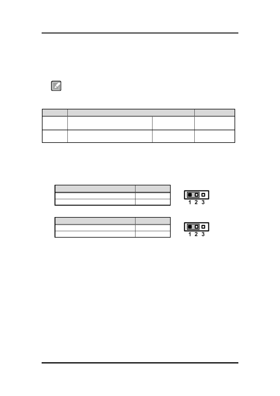
3.4.1
COM1 Data/Power Selection (JP1 and JP2)
The COM1 port has +12V level power capability on RI and +5V level on DCD by setting
JP1 and JP2, respectively. When this port is set to +12V or +5V level, please make sure
its communication mode is RS-232 (see section 6.4).
Function
JP1 Setting
Data: Set CN3 pin 18 to RI (Default)
1-2 close
Power: Set CN3 pin 18 to +12V level
2-3 close
Function
JP2 Setting
Data: Set CN3 pin 10 to DCD (Default)
1-2 close
Power: Set CN3 pin 10 to +5V level
2-3 close