Table 4-5, P5 connector signal descriptions – ADLINK VPX6000 User Manual
Page 44
32
Board Interfaces
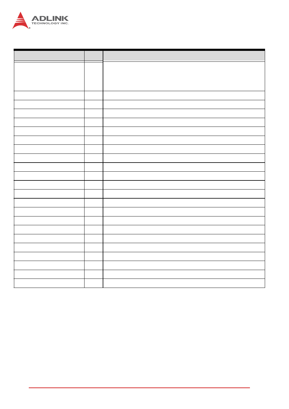
Table 4-5: P5 Connector Signal Descriptions
Signal
I/O
Description
NA_USB2-[P/N]2
NA_USB2-[P/N]4
NA_USB2-[P/N]6
NA_USB2-[P/N]8
I/O
Node A USB 2.0 port connect to PCH
NA_USBPWR[1:4]
O
USB port power +5V
NA_COM[1:2]_RTS/TXP
O
Node A Serial Comms Channel (1/2) RTS Transmit Pos
NA_COM[1:2]_TXD/TXN
O
Node A Serial Comms Channel (1/2) Transmit Data Neg
NA_COM[1:2]_CTS/RXP
I
Node A Serial Comms Channel (1/2) CTS Receive Pos
NA_COM[1:2]_RXD/RXN
I
Node A Serial Comms Channel (1/2) Receive Data Neg
NA_SATA_RX[P/N]1
I
Node A SATA 6Gb/s port receive lane from backplane to PCH
NA_SATA_TX[P/N]1
O
Node A SATA 6Gb/s port transmit lane from PCH to backplane
NA_SATA_RX[P/N]2
I
Node A SATA 6Gb/s port receive lane from backplane to PCH
NA_SATA_TX[P/N]2
O
Node A SATA 6Gb/s port transmit lane from PCH to backplane
MX[A:D]11-[P/N]
I/O
Node A 1000BASE-Tx Nodal Ethernet
NA_GLAN_KX[R/T]1_[P/N]
I/O
Node A 1Gb BASE-KX Ethernet
NA_PCH_SPKR
O
Node A audio speaker output
NA_AGND_AU
GND
Node A audio ground
NA_BP_PWRBTN-L
I
Node A power button input
NA_HP_[R/L]
O
Node A audio line output
NA_L_IN_[R/L]
I
Node A audio line input
NA_TMDSB_*
O
Node A HDMI/DVI output 1
NA_TMDSC_*
O
Node A HDMI/DVI output 2
NA_DVI_HPD[0:1]
I
Node A DVI channel 0/1 Hot Plug Detect
NA_DVI_SCL[0:1]
I/O
Node A DVI channel 0/1 DDC Clock
NA_DVI_SDA[0:1]
I/O
Node A DVI channel 0/1 DDC Data
NA_P5V_DVI
O
Node A DDC 5V