ADLINK cBP-3204[R] User Manual
Page 53
Backplane
• 43
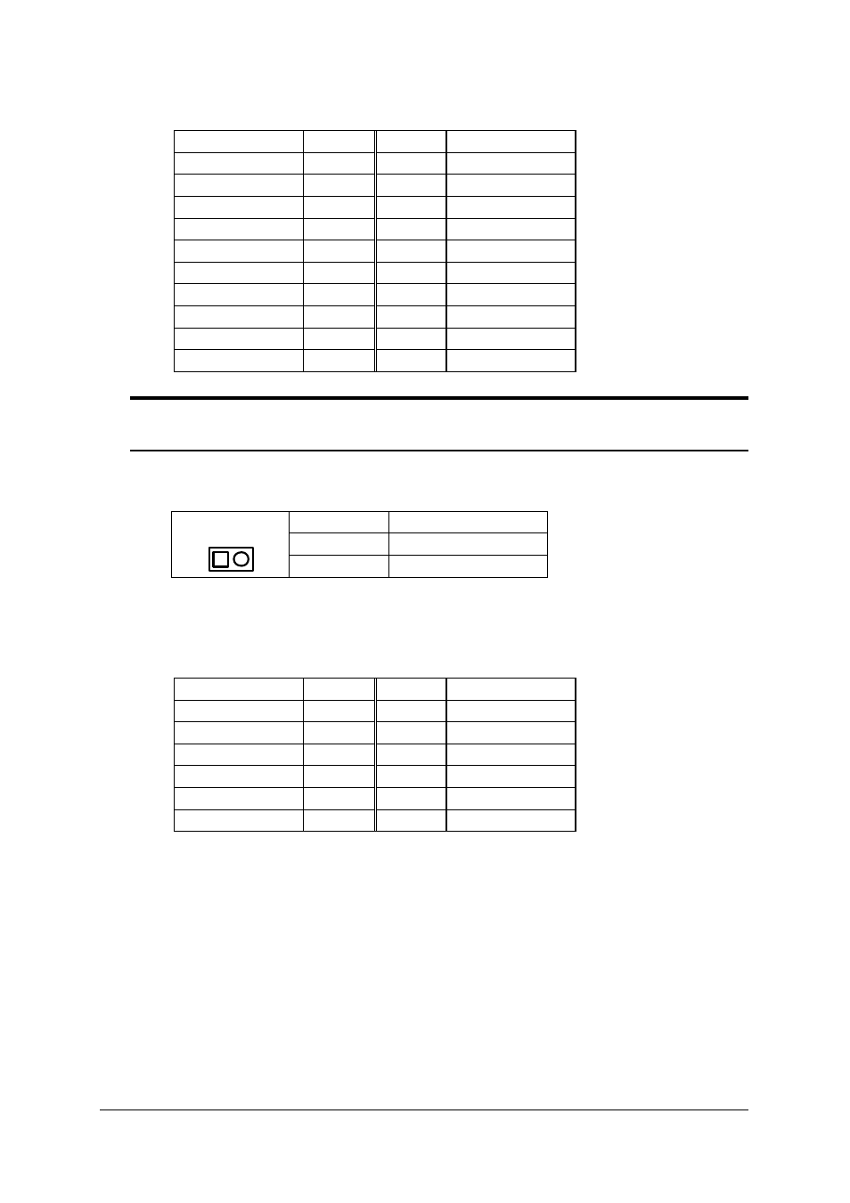
u
CN104 extended connector for power sharing
Signal
Pin No. Pin No.
Signal
V2SENSE
1
11
V2
V2
2
12
V4
GND
3
13
GND
V1
4
14
INH#
GND
5
15
GND
V1
6
16
SRTN
GND
7
17
GND
FAL#2
8*
18*
V3SENSE
DEG#2
9*
19
V1SENSE
V3
10
20
V1
Note: 1. Pin #8, #9, and #18 are not standard ATX power definition.
2. V1=+5V; V2= 3.3V; V3 = +12V; V4=-12V
u
CN105 INH#: DC power output inhibit signal. It is for inhibiting the DC
power supply. This connector can be used for power-on switch.
Pin #
Name
1
INH#
CN105
2
GND
u
CN107: Screw terminals for external AC input power lines
u
CN106: Current sharing connector, this connector is used only when
multiple power backplane is used in the same time.
Signal
Pin No. Pin No.
Signal
V1SENSE
1
2
V3SENSE
GND
3
4
V2SENSE
GA2#2
5
6
GA2#1
GA1#2
7
8
GA1#1
GA0#2
9
10
GA0#1
N/C
11
12
N/C