ADLINK cBP-3204[R] User Manual
Page 15
Chassis
• 5
•
Current control of the FAN to provide stable fan operation
•
Fan failure detection ready to use
•
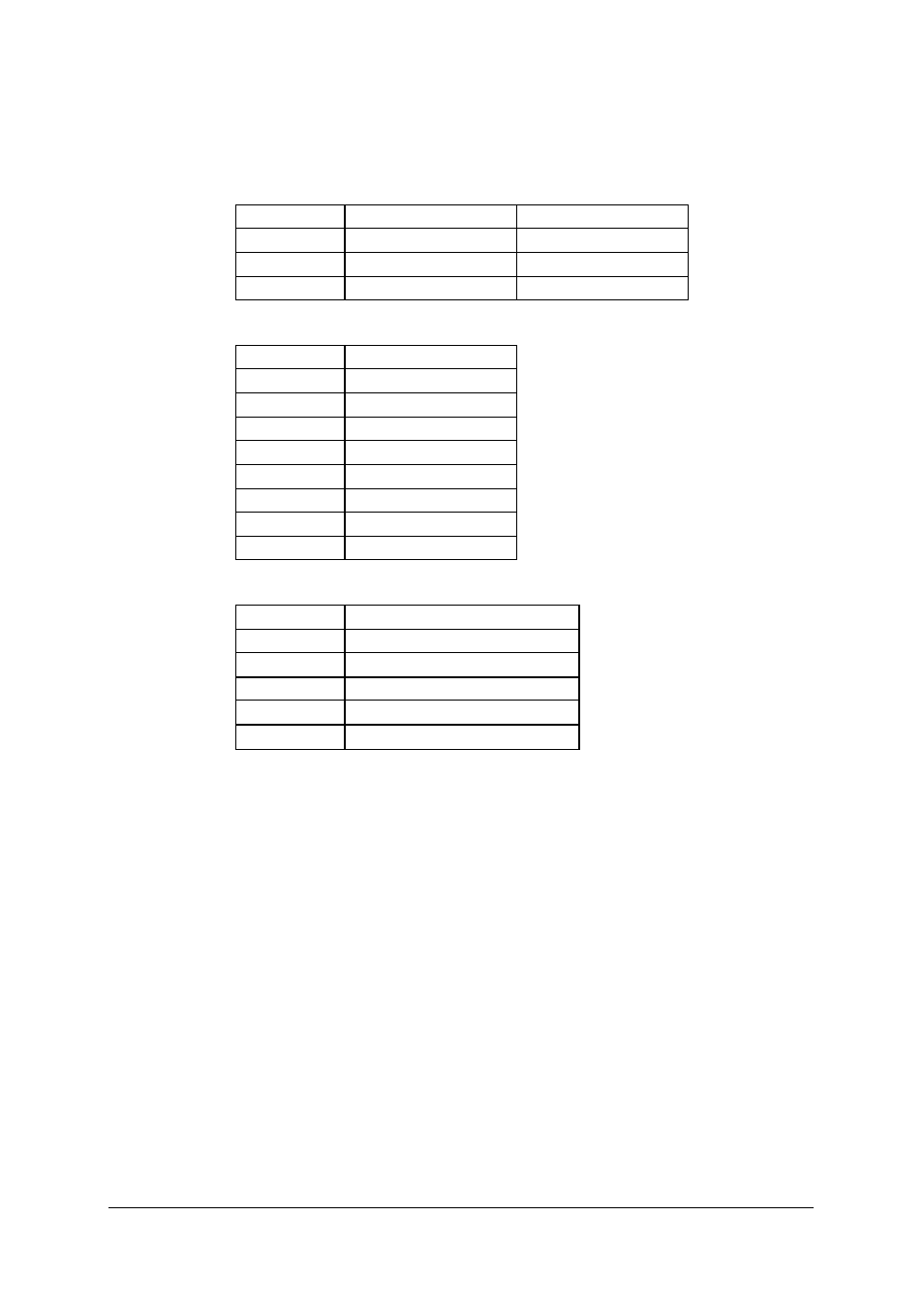
Power input connector (CN101)
Pin #
Signal
Cable color
1
-12V
Yellow
2
GND
Black
3
+5V
Red
•
Connector to Fans (CN102)
Pin #
Signal
1
GND
2
Fan #1 power
3
GND
4
Fan #2 power
5
GND
6
Fan #3 power
7
GND
8
Fan #4 power
•
Fan failure output (CN103)
Pin #
Signal
1
+5V
2
Fan #1 failure output
3
Fan #2 failure output
4
Fan #3 failure output
5
Fan #4 failure output
•
Power requirement:
n +5V: 40 mA maximum
n -12V: 200 mA plus fans’ power consumption, which is
dependent on numbers of fans