ADLINK cBP-3204[R] User Manual
Page 40
30
• Backplane
u
CN1: Standard ATX DC Power input connector
Signal
Pin No. Pin No.
Signal
+3.3V
1
11
+3.3V
+3.3V
2
12
-12V
GND
3
13
GND
+5V
4
14
PS_ON
GND
5
15
GND
+5V
6
16
GND
GND
7
17
GND
PWR_OK
8*
18
-5V
+5V SB
9*
19
+5V Sense
+12V
10
20
+5V
u
CN2: Standard PS2 DC Power input connector
u
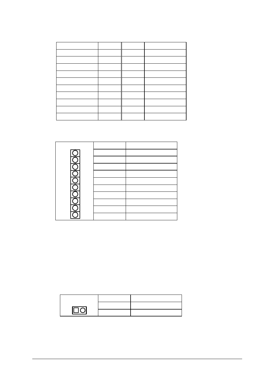
CN3: General Purpose screw terminals
Pin #
Name
1
FAL#
2
DEG#
3
-12V
4
+12V
5
GND
6
+5V
7
V(I/O)
8
+3.3V
9
GND
CN3
10
+5V
u
J1: Compliant the 31-pin CompactPCI power supply interface standard
of the PICMG 2.11. (Note: This connector is only available on the -
P version)
u
CN5: AC Input terminals for the plug-in power supply unit on J1.
(Note: This connector is only available on the -P version)
u
JP1: DC power inhibit signal, it is for inhibit the ATX PSU. This
connector is used for power-on switch which connect to the pin #14 of
CN3. When the system is using PS2 power supply, the pin 1 and pin
2 must be shorted.
Pin #
Name
1
PS_ON
JP1
2
GND
u
CN4: Power Managing Signals, the signals are from the CompactPCI
power connector J1. The pin definitions are as following.