Com1/debug switch (sw9, sw10 pins 1-2), Front/rear vga selection switch (sw10 pins 3-4) – ADLINK cPCI-6870 User Manual
Page 58
44
Board Interfaces
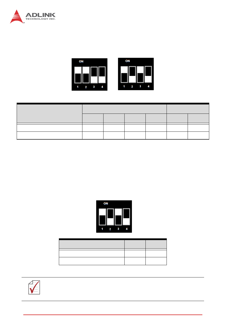
COM1/Debug Switch (SW9, SW10 pins 1-2)
Switches SW9 and SW10 (pins 1, 2) set the RJ-45 serial port (CN11)
as a standard RS-232 serial port or as an IPMI debugging port.
Table 4-28: COM1/Debug Switch Settings
Front/Rear VGA Selection Switch (SW10 pins 3-4)*
Switch SW10 (pins 3, 4) sets the VGA output to the front panel
RJ-45 port (CN11) or the VGA port on the RTM. The default
VGA output is set to rear I/O. To enable Front VGA output, the
COM/VGA Mode Selection Switches (SW7-8, SW12-13)*
must be set to VGA mode.
Table 4-29: Front/Rear VGA Selection Switch Settings
Mode
SW9
SW10
1
2
3
4
1
2
RS-232 COM port (default)
ON
ON
OFF
OFF
ON
OFF
IPMI debugging port
OFF
OFF
ON
ON
OFF
ON
Mode
3
4
Rear VGA output (default)
ON
OFF
Front VGA output
OFF
ON
NOTE:
NOTE:
*
VGA is not supported the front panel RJ-45 connector (CN11) of models with
ordering numbers ending in “xx30” and higher. On these models, SW10 is set
to “Rear VGA output” and the RJ-45 connector is a dedicated serial port.
SW9
SW10