5 jumper settings, 6 analog input channel configuration, 16 • installation – ADLINK PCM-9112+ User Manual
Page 24: Figure 2.4 analog input mode setting
16
• Installation
2.5
Jumper Settings
The following configuration can be set with jumpers: the analog input signal
mode, counter’s clock source, and analog output range. The card's jumpers
and switches are preset at the factory. You can change the jumper settings
for your own applications. The location of the jumpers are listed in the table
below
Configuration
Attributes
Jumpers
(PCI-9112
cPCI-9112R)
Jumpers
(cPCI-9112)
Analog Inputs
Single-ended or
Differential Analog
Input
JP1 and JP5
JP1 and JP4
Clock Source
Internal Clock or
External Clock
JP2 JP2
D/A Reference
Voltage
-10V or -5V
JP3
JP3
D/A Reference
Source
Internal Reference or
External Reference
JP4 JP5
Table 2.1 Jumpers Listing Table
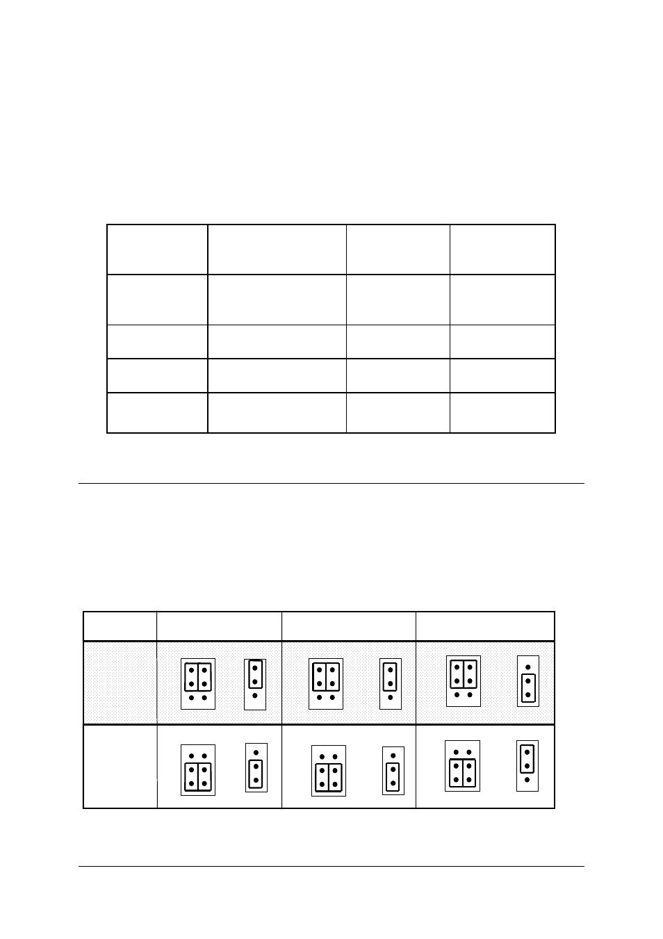
2.6 Analog Input Channel Configuration
The PCI-9112 offers 16 single-ended or 8 differential analog input channels.
Jumpers JP1 and JP5 control the analog input configurations. The settings of
JP1 and JP5 are specified below:
Differential
Input
Single-ended
(default setting)
JP5
SINGLE
DIFF
JP5
DIFF
DIFF
PCI-9112
cPCI-9112
DIFF
JP1
DIFF
JP4
SINGLE
SINGLE
SINGLE
JP1
SINGLE
DIFF
JP1
DIFF
JP4
SINGLE
SINGLE
JP1
DIFF
SINGLE
DIFF
JP1
DIFF
JP5
SINGLE
SINGLE
cPCI-9112R
DIFF
JP1
DIFF
JP5
SINGLE
SINGLE
Figure 2.4 Analog Input Mode Setting