Pre-installation preparation, Continued framing and finishing, Mantel clearances – Desa V)CD36RN User Manual
Page 7: 375 mm) 4" vertical double stud
www.desatech.com
116035-01E
7
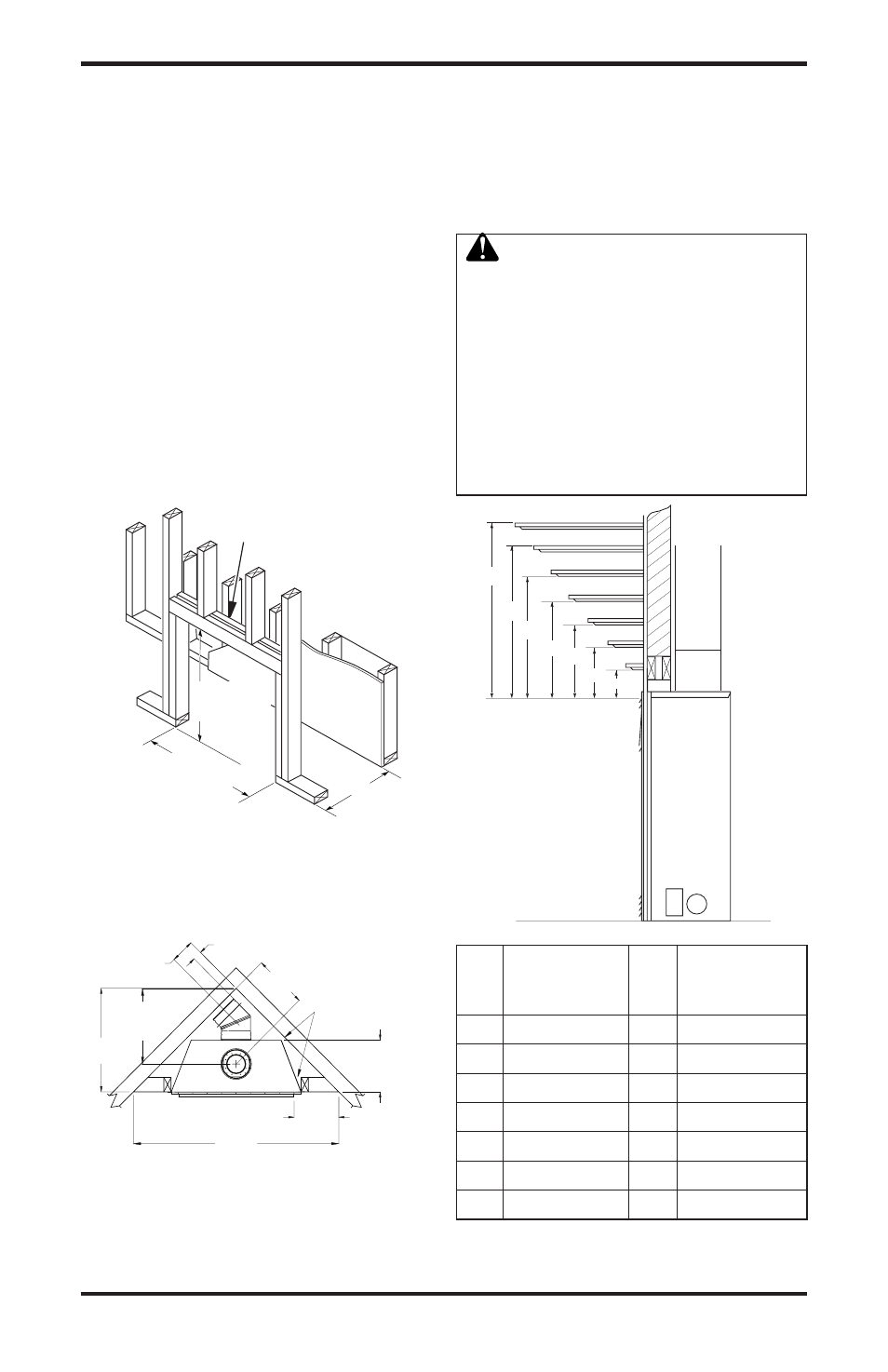
Figure 5 - Framing Clearances for
Installation Against an Exterior Wall
36"
(914 mm)
36
1
/
4
"
(91 mm)
Figure 6 - Framing Clearances for Corner
Installation
PRE-INSTALLATION
PREPARATION
Continued
FRAMING AND FINISHING
Figure 5 shows typical framing of this fireplace.
Figure 6 shows framing for corner installation. All
minimum clearances must be met.
For overall unit dimensions, framing allowances
and vent collar locations, see Unit Dimensions,
Figure 9, page 8.
For available accessories for this fireplace, see
Accessories on page 45. If you are using a separate
combustible mantel piece, refer to Figure 7 and
Figure 8, page 8 for proper height and clearances.
You can install noncombustible mantels at any
height above the fireplace.
Note:
Noncombustible mantels may discolor!
14
3
/
4
"
(375 mm)
4" Vertical
Double Stud
C
B
A
D
E
F
G
3
2
1
4
5
6
7
Ref. Mantel Depth Ref.
Mantel from
Top of Louver
Opening
1
16" (406 mm)
A
14" (356 mm)
14" (356 mm)
A
1" (305 mm)
3
1" (305 mm)
B
10" (54 mm)
4
10" (54 mm)
C
8" (03 mm)
5
8" (03 mm)
D
6" (15 mm)
6
4" (101 mm)
F
4" (101 mm)
7
" (51 mm)
G
" (51 mm)
Figure 7 - Clearances for Combustible
Mantels
MANTEL CLEARANCES
Figure 7 shows projected mantel depths at various
heights above the top of the louver opening. Figure
8, page 8, shows the minimum allowable distances
from various mantel components in relation to the
both sides of the fireplace opening.
WARNING: When finishing
appliance, do not overlap com-
bustible materials onto the black
front face. Brick, tile, or other non-
combustible materials may be
applied to the face provided that
any fireplace openings are not
blocked and gaps in the material
used and the face are sealed with
a non-combustible caulking.
14
3
/
4
"
(375 mm)
FOR 1" OF CLEARANCE
AT THE SIDES AND BACK
OF THE FIREPLACE
IS ALSO PERMITTED AT
HOWEVER, 0" CLEARANCE
ALL SIDES WHEN FRAMED
THESE DIMENSIONS ALLOW
21" (533 mm)
TO CENTER OF
TOP VENT
14
3
/
4
"
(375 mm)
TO NAILING
FLANGES
56
3
/
4
"
(1441 mm)
12
1
/
4
"
(311 mm)
TO
OPENING
28
5
/
8
"
(727 mm)
6
5
/
8
" ( 168 mm)
TO CENTER
OF REAR VENT
2
1
/
2
" (63 mm)
MIN. 1" (26 mm)