Venting installation instructions – Desa V)CD36RN User Manual
Page 19
www.desatech.com
116035-01E
19
VENTING INSTALLATION
INSTRUCTIONS
Continued
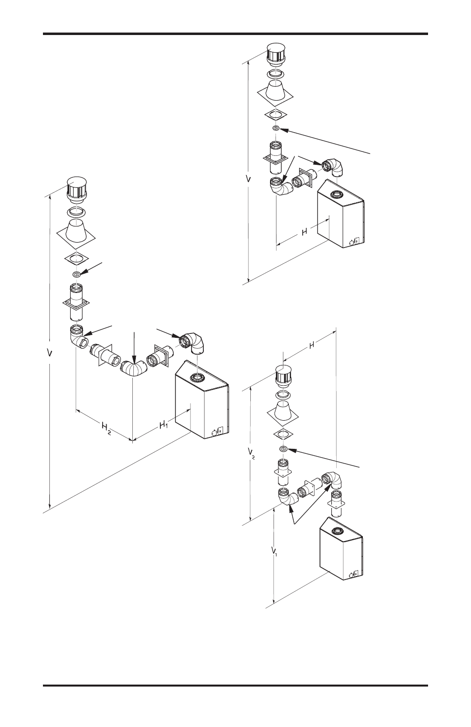
vertical Termination Configurations for
Top vent
Figures 30 and 33 show four different configura-
tions for vertical termination.
VERTICAL VENT INSTALLATIONS USING
MULTIPLE 90° ELBOWS (V)CD36T TOP
VENT
Figure 31 - Vertical Venting
Configuration Using Two 90° Elbows
(Model (V)CD36T with Vertical Round
High Wind Termination)
Figure 32 - Vertical Venting
Configuration Using Two 90° Elbows
(Model (V)CD36T with Vertical Round
High Wind Termination)
Note: Vertical (V
1
) + Vertical (V
) = 40' Max.
Max. Horizontal Above 14' Vertical = 0'
Figure 30 - Vertical Venting
Configuration using Three 90° Elbows
(Model (V)CD36T with Vertical Round
High Wind Termination)
venting with Two 90°
Elbows
vertical
(v
1
)
Horizontal
(H)
8' Min.
9' Max
9' Min.
11' Max
10' Min.
13' Max
1' Min.
17' Max
14' Min.
0' Max
venting with Three 90° Elbows
vertical (v)
Horizontal (H
1
) +
Horizontal (H
2
)
8' Min.
5' Max
10' Min.
8' Max
1' Min.
11' Max
14' Min.
14' Max
16' Min.
17' Max
18' Min.
0' Max
40' Min.
0' Max
venting with Two 90° Elbows
vertical (v)
Horizontal (H)
8' Min.
6' Max
9' Min.
8' Max
10' Min.
10' Max
1' Min.
14' Max
14' Min.
18' Max
40' Min.
0' Max
Note: Install a
VR-58 vertical
restrictor ring
into inner pipe
section prior to
attaching vent
termination
cap.
90° Elbow
90° Elbow
Note: Install a
VR-58 vertical
restrictor ring
into inner pipe
section prior to
attaching vent
termination
cap.
90° Elbow
Note: Install a
VR-58 vertical
restrictor ring
into inner pipe
section prior to
attaching vent
termination
cap.