Venting installation instructions, Continued – Desa V)CD36RN User Manual
Page 14
www.desatech.com
116035-01E
14
GROUND FLOOR INSTALLATION
Recommended Applications for Rear Vent Model
(V)CD36T:
• Installation using cabinet surrounds
• Through the wall using round or square
termination (up to 24" horizontal pipe)
• Corner installation (Using one 90° elbow and
a maximum of 24" of horizontal pipe)
VENTING INSTALLATION
INSTRUCTIONS
Continued
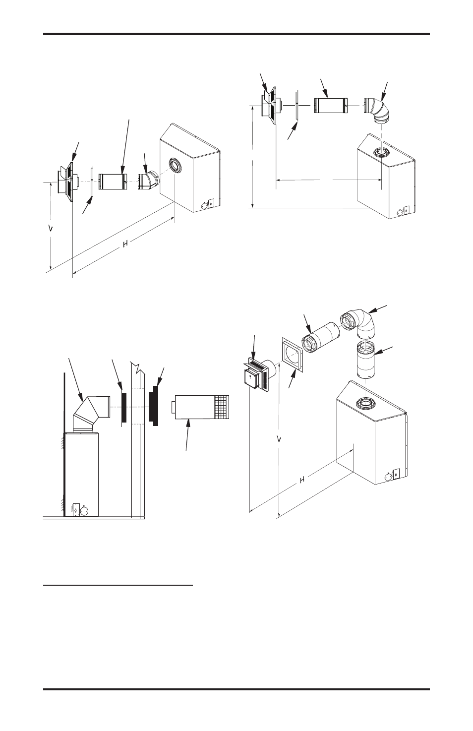
Figure 20 - Horizontal Termination
Configuration Round Termination
(Model (V)CD36T)
Figure 19 - Horizontal Termination
Configuration for Corner Installation
(Model (V)CD36R)
Figure 21 - Horizontal Termination
Configuration For Corner Installation
Using One 90° Elbow (Model (V)CD36T)
Figure 22 - Horizontal Termination
Configuration with Vertical Rise and One
90° Elbow (Model (V)CD36T)
Required
vertical (v)
vertical (v)
vertical Pipe
Allowable
Horizontal (H)
45
1
/
"
None
6" Max.
57
1
/
4
" Min.
1 ft.
30" Max.
69
1
/
4
" Min.
ft.
74" Max.
81
1
/
" Min.
3 ft.
98" Max.
94" Min.
4 ft.
1" Max.
106" Min.
5 ft.
146" Max.
159" Min.
9 ft.
0' Max.
TO
H
H
V
Horizontal Square
Termination
Wall
Firestop
Straight/Adjustable
Pipe 18" Max.
Corner Installation
vertical (v)
Horizontal (H)
5
1
/
" Min.
4" Max
45°
Elbow
Wall
Firestop
Horizontal
Round
Termination
Exterior
Portion of Wall
Firestop (Round
Termination Only)
90°
Elbow
Wall
Firestop
Straight/
Adjustable
Pipe 4" Max.
Horizontal
Square
Termination
90°
Elbow
Corner Installation
vertical (v)
Horizontal (H)
45
1
/
" Min.
3
1
/
" Max
90° Elbow
Wall
Firestop
Square
Termination
Not to Exceed
(H) Limits
As
Required
for (V),
See Chart
for Pipe
Section
Required