Venting installation instructions – Desa V)CD36RN User Manual
Page 13
www.desatech.com
116035-01E
13
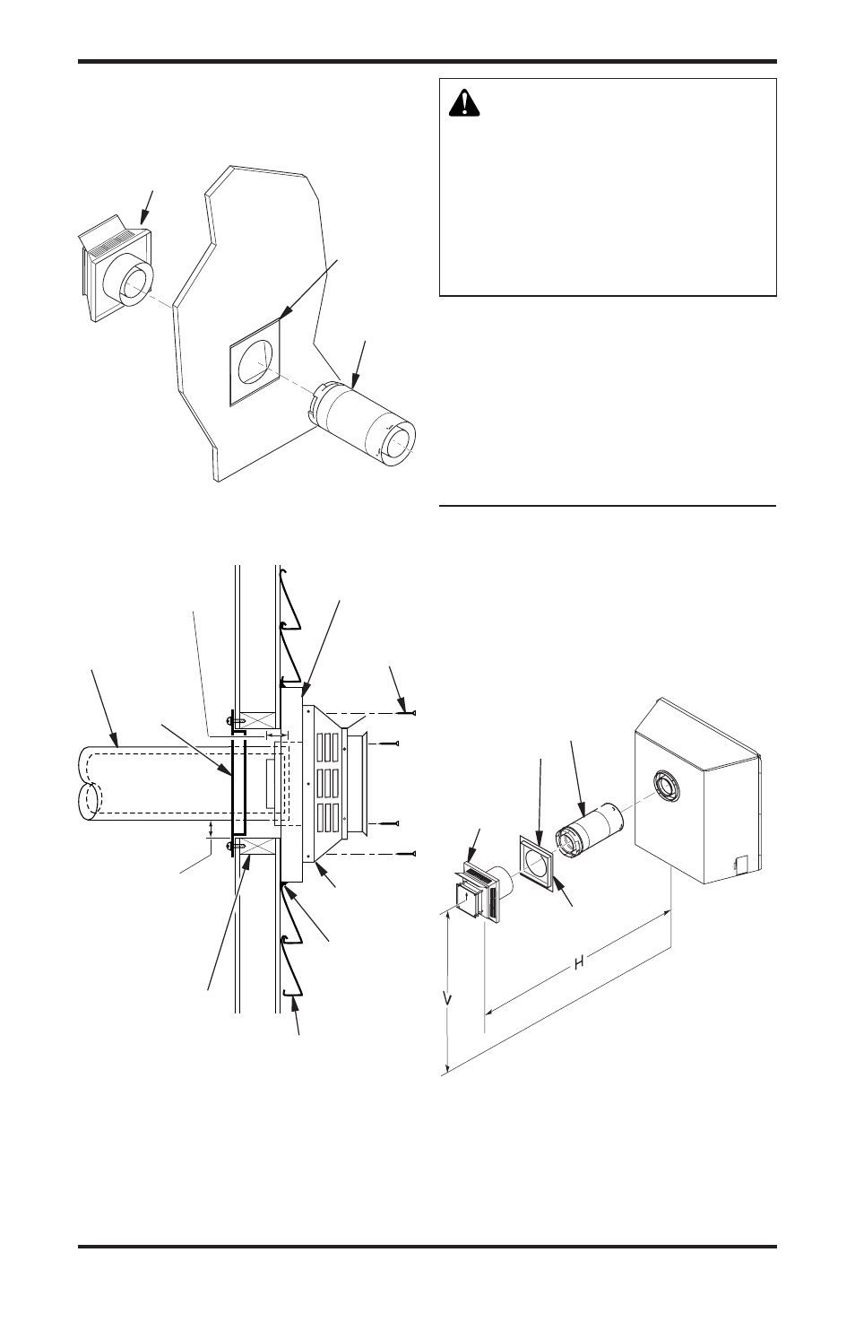
Figure 16 - Installing Inner Wall Firestop
VENTING INSTALLATION
INSTRUCTIONS
Continued
Figure 17 - Typical Horizontal
Termination Cap Mounting with
Additional Siding Standoff Installed
Siding Standoff
Screws
High Wind
Termination
Apply
Mastic to
Outside
Edge of
Standoff
Exterior Wall with Vinyl Siding
10
3
/
4
" x 10
3
/
4
"
Framed Opening
Maintain 1"
Minimum Air
Space Around
Outer Pipe When
Penetrating a Wall
Minimum Pipe
Overlap 1
1
/
4
"
Wall
Firestop
Direct-Vent
Pipe
WARNING: Never run vent
downward as this may cause
excessive temperatures which
could cause a fire. Operation of
improperly installed and main-
tained venting system could
result in serious injury, property
damage or loss of life.
Horizontal Termination Configurations
Figures 18 through 25 show different configura-
tions and alternatives for venting with horizontal
termination. Each figure includes a chart with
critical minimum and maximum dimensions which
MUST be met. IMPORTANT: Remember that a
horizontal run of venting must have a 1/4" rise for
every 12" of run toward the termination.
GROUND FLOOR INSTALLATION REAR VENT
Recommended Applications fo Rear Vent Model
(V)CD36R:
• Installation using cabinet surrounds
• Through the wall using round or square termi-
nation (up to a maximum of 18” of horizontal
pipe)
• Corner installation (Using one 45° elbow and
a maximum of 18" of horizontal pipe).
Figure 18 - Horizontal Termination
Configureation for Flush Installation
(Model (V)CD36R)
TO
H
Inner Wall
Firestop
Vent
Cap
Pipe
Section
Horizontal
Square
Termination
Wall Firestop
Straight/Adjustable
Pipe 18" Max.
Square Termination
vertical (v)
Horizontal (H)
5
1
/
" Min.
" Max