Venting installation instructions – Desa V)CD36RN User Manual
Page 15
www.desatech.com
116035-01E
15
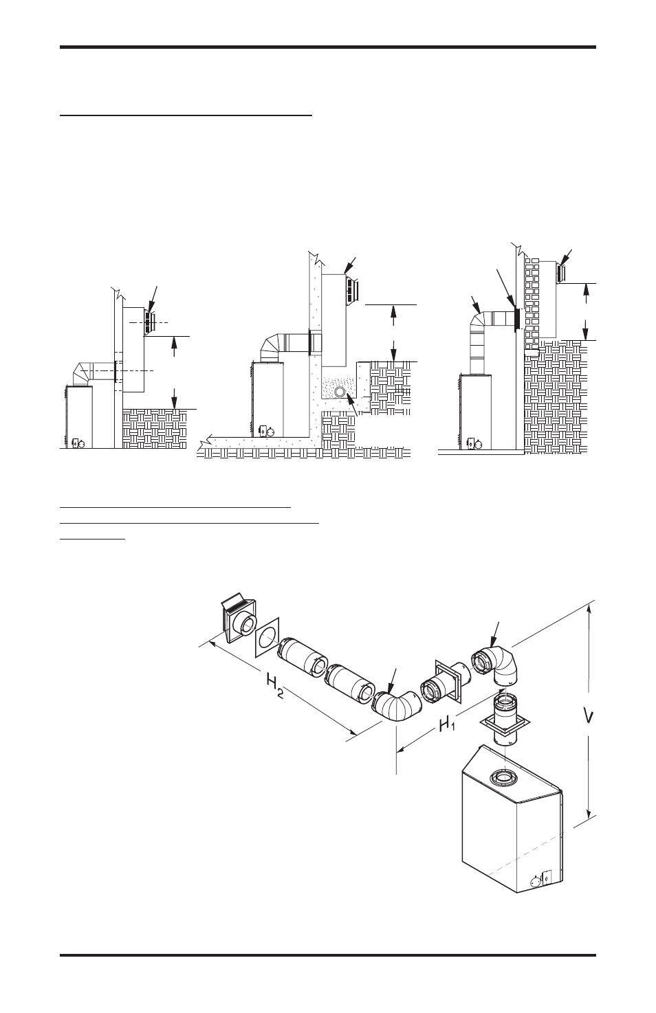
SNORKEL TERMINATION INSTALLATION
Recommended Applications Models (V)CD36R
and (V)CD36T:
• Installations requiring vertical rise on building
exterior.
• Installation using snorkel termination to achieve
1 ft. above grade.
VENTING INSTALLATION INSTRUCTIONS
Continued
Figure 23 - Snorkel Termination Configuration For Below Ground Installation
HORIZONTAL VENT INSTALLATIONS
USING MULTIPLE 90° ELBOWS (V)CD36T
TOP VENT
The following configurations show the minimum
vertical rise requirements for a horizontal system
using two 90° elbows.
Figure 24 - Horizontal Termination Configuration For Venting Using Two 90° Elbows
(Model (V)CD36T)
venting with Two 90° Elbows
vertical (v)
Horizontal (H)+
Horizontal (H
2
)
7' Min.
10' Max
8' Min.
1' Max
9' Min.
14' Max
10' Min.
16' Max
11' Min.
18' Max
13' Min.
0' Max
Snorkel terminations are available for installations
requiring a vertical rise on the exterior of the build-
ing. If installing snorkel below grade
you must provide proper drainage to prevent water
from entering snorkel (see Figure 23, page 15). Do
not back fill around snorkel termination.
90°
Elbow
90°
Elbow
Snorkel
Termination
1"
Min.
1" Min.
Adequate
Drainage
Snorkel
Termination
Snorkel
Termination
90° Elbow
1" Min.
Wall
Firestop